Description
 Stormwater filtering practices capture and store stormwater runoff and pass it through a filtering media such as sand, organic material, or soil for pollutant removal. Stormwater filtering practices generally fall into two categories, which are described in this section:
- Surface filters (including bioretention)
- Underground filters
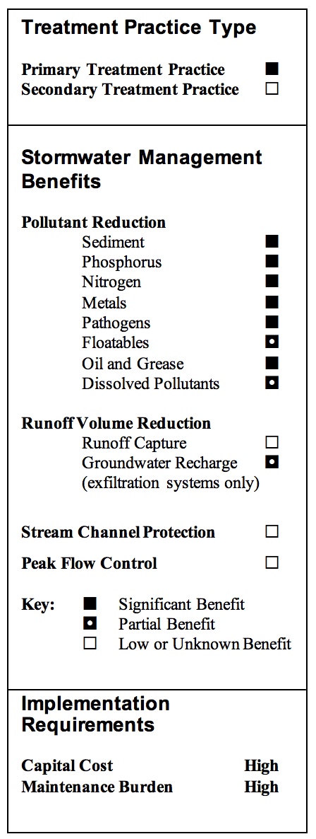
Stormwater filters are primarily water quality control devices designed to remove particulate pollutants and, to a lesser degree, bacteria and nutrients. A separate facility would typically be required to provide channel protection and peak flow control. Most filtering systems consist of four design components:
- Inflow regulation to divert the water quality volume into the structure
- Pretreatment to capture coarse sediments
- Filter surface and media
- Outflow mechanism to return treated flows back to the conveyance system or into the soil
Stormwater filtering practices are typically applied to small drainage areas (5 to 10 acres) and designed as off-line systems to treat the water quality volume and bypass larger flows. The water quality volume is diverted into a pretreatment settling chamber or forebay where coarse solids are allowed to settle, thereby reducing the amount of sediment that reaches the filter. Water flows to the filter surface in a controlled manner, where finer sediment and attached pollutants are trapped or strained out and microbial breakdown of pollutants (i.e., nitrification) can occur. Filtered stormwater is then collected below the filter bed or media and either returned to the conveyance system via an underdrain or allowed to infiltrate into the soil (i.e., exfiltration). Due to their similarity to infiltration basins, which were discussed in the previous section, exfiltration systems are not addressed in this section.
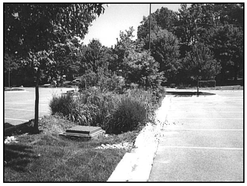
Stormwater filtering practices are commonly used to treat runoff from small sites such as parking lots and small developments, areas with high pollution potential such as industrial sites, or in highly urbanized areas where space is limited. A number of surface and underground stormwater filter design variations have been developed for these types of applications. Underground filters can be placed under parking lots and are well-suited to highly urbanized areas or space-limited sites since they consume no surface space. As such, stormwater filters are often suitable for retrofit applications where space is typically limited. Stormwater filtration systems that do not discharge to the soil (i.e., contained in a structure or equipped with an impermeable liner) are also suitable options for treating runoff from industrial areas and other land uses with high pollutant potential since the water is not allowed to infiltrate into the soil and potentially contaminate groundwater.
Design Variations
Surface Filters
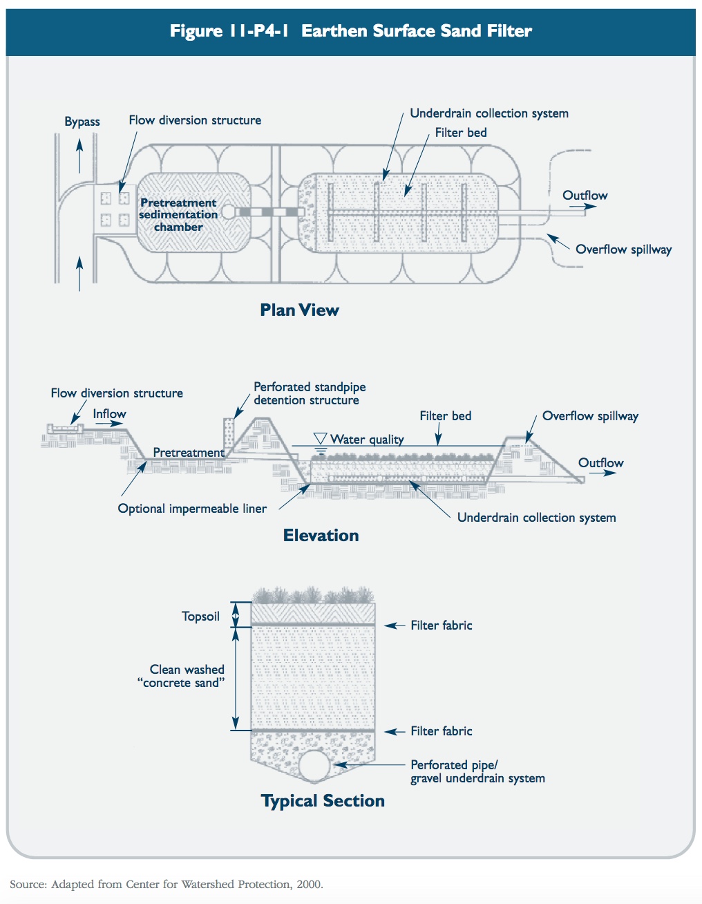
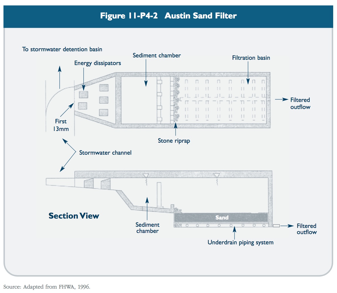
- Surface Sand Filter: The surface sand filter is the original sand filter design, in which both the filter bed and sedimentation chamber are aboveground. Surface sand filters can consist of excavated, earthen basins or aboveground concrete chambers (i.e., Austin Sand Filter). Figure 11-P4-1 and Figure 11-P4-2 depict schematics of two common surface sand filter designs.
- Organic Filters: Organic filters are similar to surface sand filters, with the sand medium replaced with or supplemented by material having a higher organic content such as peat or compost. Organic filters are generally ineffective during the winter in cold climates because they retain water and consequently freeze solid and become completely impervious. Organic filters are not recommended for use in Connecticut and, therefore, are not addressed in this manual.
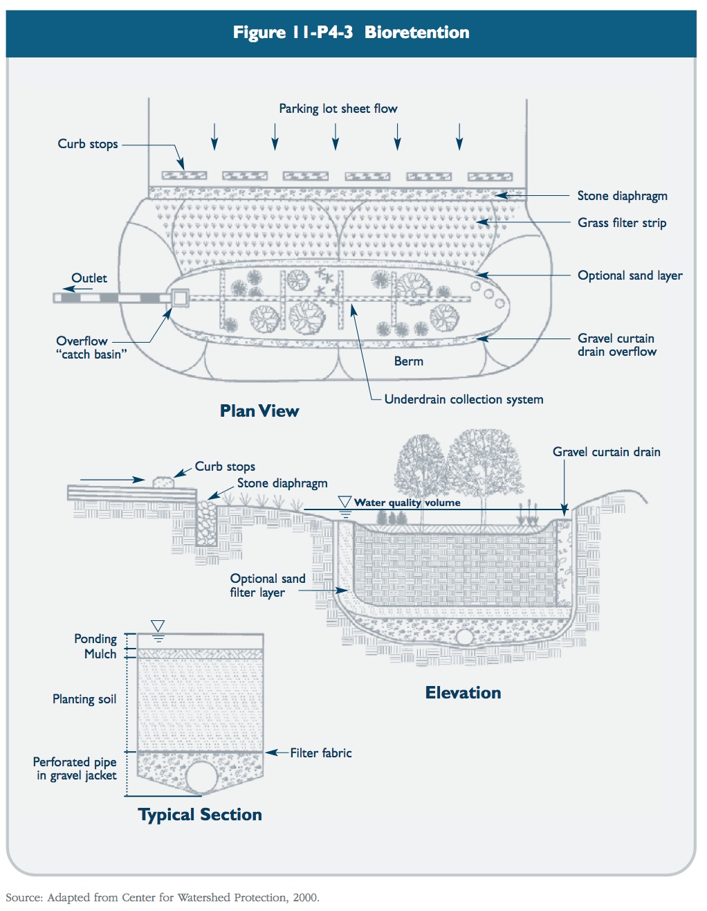
- Bioretention: Bioretention systems are shallow landscaped depressions designed to manage and treat stormwater runoff. Bioretention systems are a variation of a surface sand filter, where the sand filtration media is replaced with a planted soil bed designed to remove pollutants through physical and biological processes (EPA, 2002). Stormwater flows into the bioretention area, ponds on the surface, and gradually infiltrates into the soil bed. Treated water is allowed to infiltrate into the surrounding soils or is collected by an underdrain system and discharged to the storm sewer system or receiving waters. Small-scale bioretention applications (i.e., residential yards, median strips, parking lot islands), commonly referred to as rain gardens, are also described in Chapter Four of this manual as a Low Impact Development design practice. Figure 11-P4-3 depicts schematic designs of several common types of bioretention facilities.
Underground Filters
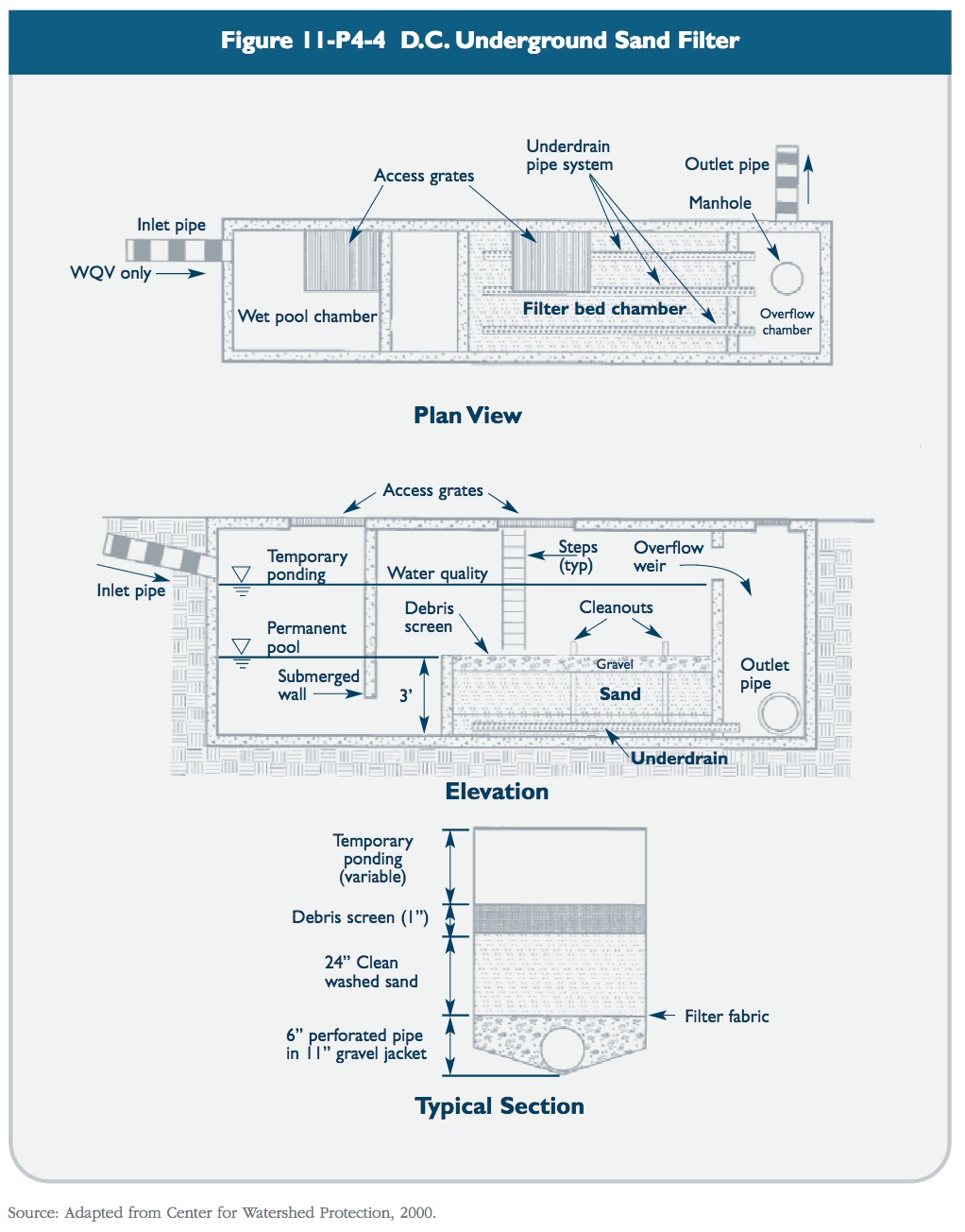
- C. Sand Filter: This underground vaulted filter design was developed by the District of Columbia in the late 1980s. The D.C. Sand Filter includes three chambers. The first chamber and a portion of the second chamber contain a permanent pool of water, which provides sedimentation and removal of floatables and oil and grease. Water flows through a submerged opening near the dividing wall that connects the two chambers, into the second chamber and onto the filter bed. Filtered water is collected by an underdrain system and flows into the third chamber, which acts like a clearwell and overflow chamber (EPA, 2002). A schematic of the D.C. Sand Filter is shown in Figure 11-P4-4.
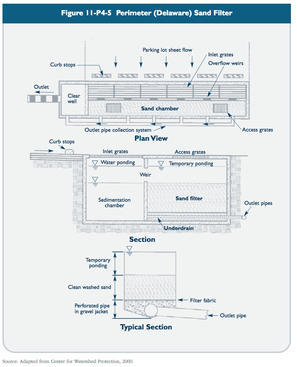
- Perimeter Sand Filter: The perimeter sand filter is an underground vault sand filter that was originally developed in Delaware (also known as the “Delaware Sand Filter”) for use around the perimeter of parking lots. The system contains two parallel chambers and a clearwell. Overland flow enters the first chamber through slotted grates, which acts as a sedimentation chamber. Water then flows over weirs into the second chamber, which contains the filter media. Filtered water is collected by an underdrain system and flows into a clearwell before discharging to the storm drain system. A schematic of a perimeter sand filter is shown in Figure 11-P4-5.
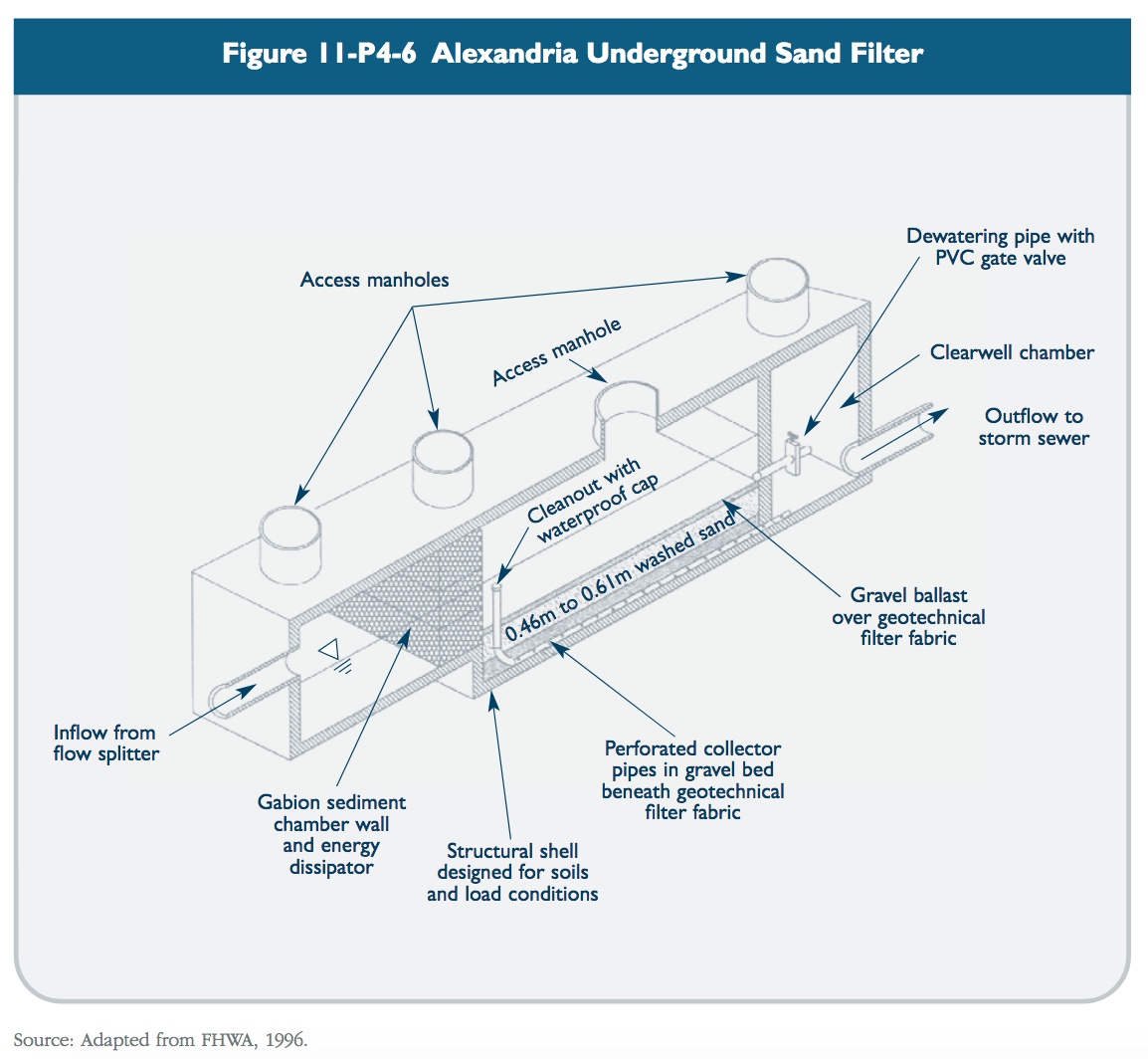
- Alexandria Sand Filter: The Alexandria Sand Filter, developed in Alexandria, Virginia, is similar to the D.C. Sand Filter in that it consists of three distinct chambers, a sediment chamber, a filtering chamber, and a clearwell. However, the Alexandria design replaces the permanent pool oil/water separator with a gabion barrier that filters and dissipates energy. This variation is a dry system designed to drain between storms. Figure 11-P4-6 shows a schematic of an Alexandria Sand Filter.
- Proprietary Designs: A number of proprietary underground media filter designs have been developed in recent years. These systems consist of the same general configuration, with specialized filter media targeted at removal of various particulate and soluble pollutants. Most of these pre-manufactured systems consist of a sedimentation chamber and a filtration chamber that holds a series of canisters with replaceable/recyclable media cartridges. These systems currently are not considered primary treatment practices due to limited peer-reviewed data on their performance under field conditions. Proprietary filtering designs are discussed further as secondary treatment practices later in this chapter.
Design Criteria
The design criteria presented in this section are applicable to surface sand filters, bioretention systems, and underground filters. Considerations for specific design variations are also included.
Pretreatment
* Pretreatment should be provided to store at least 25 percent of the water quality volume and release it to the filter media over a 24-hour period. Storage and pretreatment of the entire water quality volume (also known as “full sedimentation” design) may be required for sites with less than 75 percent imperviousness or sites with unusually high sediment loads.
* Pretreatment generally consists of a dry or wet sedimentation chamber or sediment forebay. A length-to-width ratio of between 1.5:1 and 3:1 is recommended for the pretreatment area.
* The required surface area of the sedimentation chamber or forebay for full sedimentation design can be determined using the following (Camp-Hazen) equation:
As = - Q/W ln (1-E)
where:
| As | = sedimentation surface area (ft2) |
| Q | = discharge rate from drainage area (ft3/s) = WQV/24hr* |
| W | = particle settling velocity (0.0004 ft/s recommended for silt |
| E | = sediment removal efficiency (assume 0.9 or 90%) |
| * (between 25 and 100% of the water quality volume can be used for partial sedimentation design) |
Design Volume
* Surface sand filters should provide at least 75 percent of the water quality volume in the practice (including above the filter, in the filter media voids, and in the pretreatment chamber) and be designed to completely drain in 24 hours or less.
Filter Bed
* The filter media for a surface sand filter should consist of medium sand (ASTM C-33 concrete sand). Grain size analysis provided by the supplier is recommended to confirm the sand specification. However, if other media are desired to address specific pollutants, pilot testing is recommended to determine actual hydraulic conductivity.
* The required filter bed area should be calculated using the principles of Darcy’s Law, which relates the velocity of porous media flow to the hydraulic head and hydraulic conductivity of the filter medium:
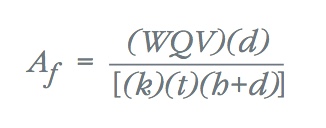
where:
| Af | = filter bed surface area (ft2) |
| WQV | = water quality volume (ft3) |
| d | = filter bed depth (ft) |
| k | = hydraulic conductivity of filter media (ft/day) |
| t | = time for the water quality volume to drain from the system (24 hours) |
| h | = average height of water above filter bed during water quality design storm |
* A typical hydraulic conductivity value for medium sand is 3.5 feet per day. Laboratory analysis is recommended to determine the hydraulic conductivity of the actual filter media.
* The recommended minimum filter bed depth is 18 inches. Consolidation of the filter media should be taken into account when measuring final bed depth. The surface of the filter bed should be level to ensure equal distribution of flow in the bed.
* Mosquito entry points to underground filter systems should be sealed (adult female mosquitoes can use openings as small as 1/16 inch to access water for egg laying).
Underdrain System
* The underdrain system should consist of 6-inch diameter or larger PVC perforated pipes reinforced to withstand the weight of the overburden (schedule 40 PVC or greater). A central collector pipe with lateral feeders is a common underdrain piping configuration. The main collector underdrain pipe should have a minimum slope of one percent. The maximum distance between two adjacent lateral feeder pipes is 10 feet.
* Perforations in the underdrain piping should be half-inch holes spaced 6 inches apart longitudinally, with rows 120 degrees apart (Metropolitan Council, 2001).
* The underdrain piping should be set in 1 to 2-inch diameter stone or gravel washed free of fines and organic material. The stone or gravel layer should provide at least 2 inches of coverage over the tops of the drainage pipes. The stone or gravel layer should be separated from the filter media by a permeable geotextile fabric. Geotextile fabric (and an impermeable liner if necessary, see below) should also be placed below the stone or gravel layer.
* Cleanouts should be provided at both ends of the main collector pipe and extend to the surface of the filter.
Impermeable Liner
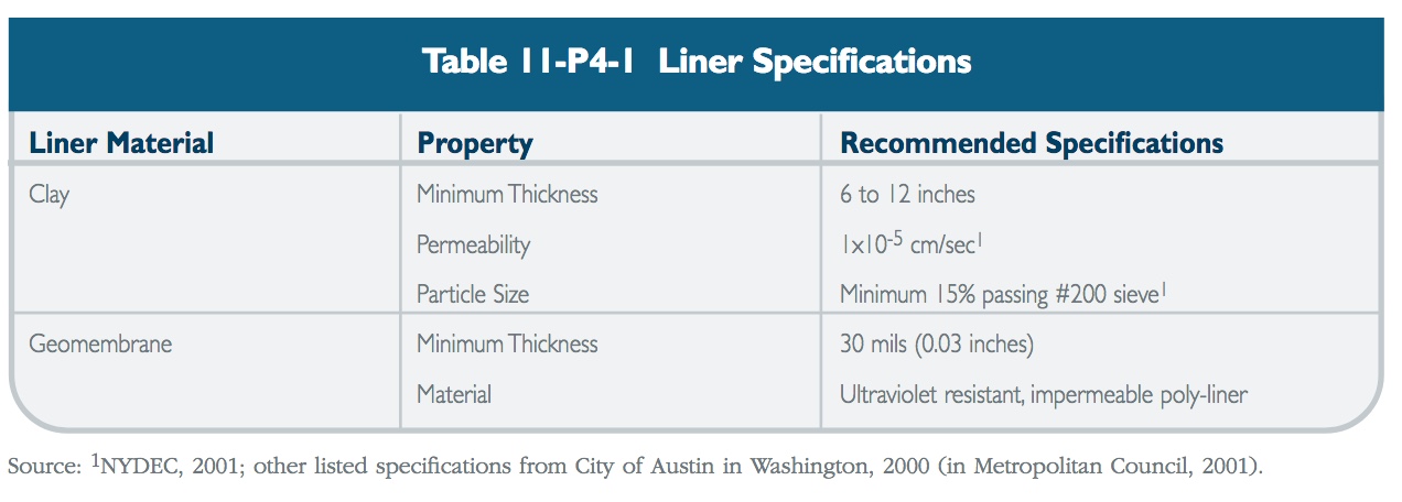
* An impermeable liner (clay, geomembrane, or concrete) should be used for excavated surface sand filters when infiltration below the filter or pretreatment area could result in groundwater contamination, such as in aquifer protection areas or in areas with the potential for high pollutant loads (e.g. soluble metals and organics). Table 11-P4-1 lists recommended specifications for clay and geomembrane liners.
Conveyance
* A flow diversion structure should be provided to divert the water quality volume to the filtering practice and allow larger flows to bypass the system.
* An overflow should be provided within the filtering practice to pass the 10-year design storm to the storm drainage system or stabilized channel.
* Inlet structures should be designed to minimize turbulence and spread flow uniformly across the surface of the filter.
* Stone riprap or other velocity dissipation methods should be used at the inlet to the filter bed to prevent scour of the filter media.
Landscaping/Vegetation
* Planting of surface filters with a grass cover is not recommended since grass clippings can result in reduced permeability or clogging of the filter surface. Grass cover can also conceal the treatment structure or cause it to blend in with surrounding vegetation, thereby potentially resulting in decreased maintenance (i.e., out-of-sight, out-of-mind).
* Bioretention facilities generally consist of the following hydric zones (Claytor and Schueler, 1996):
- Lowest Zone: The lowest zone supports plant species adapted to standing and fluctuating water levels and corresponds to hydrologic zones 2 and 3 in Table A-1 of Appendix A.
- Middle Zone: The middle zone supports a slightly drier group of plants, but still tolerates fluctuating water levels. This zone corresponds to hydrologic zones 3 and 4 in Table A-1 of Appendix A.
- Outer Zone: The outer or highest zone generally supports plants adapted to drier conditions. This zone corresponds to hydrologic zones 5 and 6 in Table A-1 of Appendix A.
Plants should be selected to simulate a terrestrial forested community of native species. The following planting plan design considerations should be followed for bioretention areas (Claytor and Schueler, 1996).
- Use native plant species
- Select vegetation based on hydric zones
- Plant layout should be random and natural
- Establish canopy with an understory of shrubs and herbaceous plants
- Do not use woody vegetation near inflow locations
- Plant trees along the perimeter of the bioretention area
- Do not specify noxious weeds
- Wind, sun, exposure, insects, disease, aesthetics, existing utilities, traffic, and safety issues should be considered for plant selection and location.
Winter Operation
* Surface sand filters and perimeter filters can be ineffective during the winter months due to freezing of the filter bed.
* Where possible, the filter bed should be below the frost line.
* A larger underdrain system (i.e., larger diameter and more frequently spaced underdrain pipes and stone or gravel) may encourage faster draining and reduce the potential for freezing during winter months.
* Filters that receive significant road sand should be equipped with a larger pretreatment sediment chamber or forebay.