Infiltration Practices (2004)

Description

Stormwater infiltration practices are designed to capture stormwater runoff and infiltrate it into the ground over a period of days.   This section includes two types of infiltration practices:

  • Infiltration Trench
  • Infiltration Basin.

Infiltration practices reduce runoff volume, remove fine sediment and associated pollutants, recharge groundwater, and provide partial attenuation of peak flows for storm events equal to or less than the design storm. Infiltration practices are appropriate for small drainage areas, but can also be used for larger multiple lot applications, in contrast to rain gardens and dry wells, which are primarily intended for single lots.

Infiltration trenches are shallow, excavated, stone-filled trenches in which stormwater is collected and infiltrated into the ground.  Infiltration trenches can be constructed at a ground surface depression to intercept overland flow or can receive piped runoff discharged directly into the trench.  Runoff gradually percolates through the bottom and sides of the trench, removing pollutants through sorption, trapping, straining, and bacterial degradation or transformation.

Infiltration basins are stormwater impoundments designed to capture and infiltrate the water quality volume over several days, but do not retain a permanent pool. Infiltration basins can be designed as off-line devices to infiltrate the water quality volume and bypass larger flows to downstream flood control facilities or as combined infiltration/flood control facilities by providing detention above the infiltration zone.  This section describes off-line basins designed for groundwater recharge and stormwater quality control, rather than flood control.  The bottom of an infiltration basin typically contains vegetation to increase the infiltration capacity of the basin, allow for vegetative uptake, and reduce soil erosion and scouring of the basin.

A number of underground infiltration structures, including premanufactured pipes, vaults, and modular structures, have been developed in recent years as an alternative to infiltration trenches and basins for space-limited sites and stormwater retrofit applications.  Performance of these systems varies by manufacturer and system design.  These systems are currently considered secondary treatment practices due to limited field performance data, although pollutant removal efficiency is anticipated to be similar to that of infiltration trenches and basins.

Infiltration practices are susceptible to clogging by suspended solids in stormwater runoff. Therefore, infiltration trenches and basins require pretreatment to remove a portion of the solids load before entering the infiltration practice.  Infiltration trenches and basins are often preceded by other primary or secondary treatment practices that are effective in removing coarse solids, as well as oil, grease, and floatable organic and inorganic material. Infiltration practices are not appropriate in areas that contribute high concentrations of sediment, hydrocarbons, or other floatables without adequate pretreatment.

Because infiltration practices recharge stormwater directly to groundwater, they can potentially contaminate groundwater supplies with dissolved pollutants contained in stormwater runoff or mobilized from subsurface contamination. Runoff sources that cause particular problems for infiltration structures include sites with high pesticide levels, manufacturing and industrial sites due to potentially high concentrations of soluble toxicants and heavy metals, and snowmelt runoff because of salts.  Infiltration practices should be carefully sited and designed to minimize the risk of groundwater contamination.  Runoff from residential areas (rooftops and lawns) is generally considered the least polluted and, therefore, the safest runoff for discharge to infiltration structures (Wisconsin DNR, 2000).

Advantages

  • Promote groundwater recharge and baseflow in nearby streams.
  • Reduce the volume of runoff, thereby reducing the size and cost of downstream drainage and stormwater control facilities.
  • Provide partial attenuation of peak flows, thereby reducing local flooding and maintaining streambank integrity.
  • Appropriate for small or space-limited sites.

Limitations

  • Potential failure due to improper siting, design (including inadequate pretreatment), construction, and maintenance. Infiltration basins usually fail for one or more of the following reasons (Wisconsin DNR, 2000):
    • Premature clogging
    • A design infiltration rate greater than the actual infiltration rate
    • Because the basin was first used for site construction erosion control
    • Soil was compacted during construction
    • The upland soils or basin walls were not stabilized with vegetation, and sediment was delivered to the basin
  • Potential for mosquito breeding due to standing water in the event of system failure.
  • Risk of groundwater contamination depending on subsurface conditions, land use, and aquifer susceptibility.
  • Require frequent inspection and maintenance.
  • Not suitable for stormwater runoff from land uses or activities with the potential for high sediment or pollutant loads without pretreatment sized to treat the entire water quality volume.
  • Low removal of dissolved pollutants in very coarse soils.
  • Use generally restricted to small drainage areas.
  • Significantly reduced performance in the winter due to frozen soils.
  • Failure is not readily apparent until the system is severely compromised.
  • Visual inspection alone may not detect problems.

Siting Considerations

  • Drainage Area:The maximum contributing drainage area for infiltration trenches should not exceed 5 acres (2 acres is recommended). The maximum contributing drainage area for infiltration basins should not exceed 25 acres (10 acres is recommended). While theoretically feasible, provided sufficiently permeable soils, infiltration from larger contributing drainage areas can lead to problems such as groundwater mounding, clogging, and compaction.


  • Soils:Underlying soils should have a minimum infiltration rate of 0.3 inches per hour, as initially determined from NRCS soil textural classifications (Table 11-P3-1), and subsequently confirmed by a field investigation acceptable to the review authority. Soils should generally have a clay content of less than 30 percent and a silt/clay content of less than 40 percent. Suitable soils generally include sand, loamy sand, sandy loam, loam, and silt loam. Recommended soil investigation procedures include:
    • Infiltration rates should be determined through an appropriate field permeability test that is representative of vertical water infiltration through the soil, excluding lateral flows. A double-ring infiltrometer or similar test is recommended (ASTM, 1994). Other field investigation methods acceptable to the review authority may be used.
    • Lab permeability testing should not be used to establish field infiltration rates since they do not adequately represent in-situ or field conditions. Percolation tests used for designing septic systems are generally not suitable for determining field infiltration rates, but may be used as a screening tool to determine whether a site is suitable for stormwater infiltration practices.
    • Field measured infiltration rates should be reduced by a safety factor to account for clogging over time. The recommended design infiltration rate is equal to one-half the field-measured infiltration rate (i.e., safety factor of 2).
    • Test pits or soil borings should be used to determine depth to groundwater, depth to bedrock (if within 4 feet of proposed bottom of infiltration structure), and soil type.
    • Test pits or soil borings should be excavated or dug to a depth of 4 feet below the proposed bottom of the facility.
    • Infiltration tests, soil borings, or test pits should be located at the proposed infiltration facility to identify localized soil conditions.
    • Testing should be performed by a qualified professional (registered Professional Engineer, Professional Geologist, or Certified Soil Scientist licensed in the State of Connecticut).
    • For infiltration trenches, one infiltration test and one test pit or soil boring should be performed per 50 linear feet of trench. A minimum of two infiltration tests and test pits or soil borings should be taken at each trench. The design should be based on the slowest rate obtained from the infiltration tests performed at the site.
    • For infiltration basins, one infiltration test and one test pit or soil boring should be performed per 5,000 square feet of basin area. A minimum of three infiltration tests and test pits or soil borings should be performed at each basin. The design of the basin should be based on the slowest rate obtained from the infiltration tests performed at the site.


The field infiltration rate is approximately equal to the hydraulic conductivity of the soil under the following conditions:

  • Steady infiltration under saturated conditions (hydraulic gradient equal to 1)
  • Water table does not encroach above the bottom of the infiltration structure


Table 11-P3‑1. Minimum Infiltration Rates of NRCS Hydrologic Soil Groups

Group


Soil Texture

Minimum Infiltration Rate (in/hr)
A Sand, loamy sand, or sandy loam 0.30 – 0.45
B Silt loam or loam 0.15 – 0.30
C Sandy clay loam 0.05 – 0.15
D Clay loam, silty clay loam, sandy clay, silty clay, or clay 0 – 0.05

Note: Tabulated infiltration rates are approximately equal to saturated hydraulic conductivities.

Source: U.S. Soil Conservation Service, 1986.


  • Land Use:Infiltration practices should not be used to infiltrate runoff containing significant concentrations of soluble pollutants that could contaminate groundwater, without adequate pretreatment. Land uses or activities that typically generate stormwater with higher pollutant loads are identified in Chapter Seven. Infiltration practices should not be used in areas of existing subsurface contamination, and may be prohibited or restricted within aquifer protection areas or wellhead protection areas at the discretion of the review authority.


  • Slopes:Infiltration basins are not recommended in areas with natural slopes greater than 15 percent, and should be located at least 50 feet from slopes greater than 15 percent since steep slopes can cause water leakage in the lower portions of the basin and may reduce infiltration rates due to lateral water movement.


  • Water Table:The bottom of the infiltration facility should be located at least 3 feet above the seasonally high water table or bedrock, as documented by on-site soil testing.


  • Miscellaneous:Infiltration practices should not be placed over fill materials and should be located at least 100 feet away from:
    • Drinking water supply wells
    • Septic systems (any components)
    • Surface water bodies
    • Building foundations (at least 100 feet upgradient and at least 25 feet downgradient from building foundations).

Design Criteria

Design considerations for infiltration trenches and basins are presented below and summarized in Table 11-P3-2.


Table 11-P3‑2. Design Criteria for Infiltration Practices

Parameter


Design Criteria
Design Volume Entire water quality volume (WQV)
Pretreatment Volume 25% of WQV
Maximum Draining Time 48 to 72 hours after storm event (entire WQV)
Minimum Draining Time 12 hours (for adequate pollutant removal)
Maximum Contributing Drainage Area Trench: 5 acres (2 recommended)

Basin: 25 acres (10 recommended)

Minimum Infiltration Rate 0.3 in/hr (as measured in the field), lower infiltration rates may be acceptable provided sufficient basin floor area is provided to meet the required WQV and drain time
Maximum Infiltration Rate 5.0 in/hr (as measured in the field); pretreatment required for infiltration rates over 3.0 in/hr
Depth Trench: 2 to 10 feet (trench depth)

Basin: 3 feet (ponding depth) recommended, unless used as combined infiltration and flood control facilities

Source: Adapted from Wisconsin Department of Natural Resources, 2000; NYDEC, 2001; Metropolitan Council, 2001; MADEP, 1997; Lee et al., 1998.

Infiltration Trench

Figure 11-P3-1 depicts a typical schematic design of an infiltration trench.


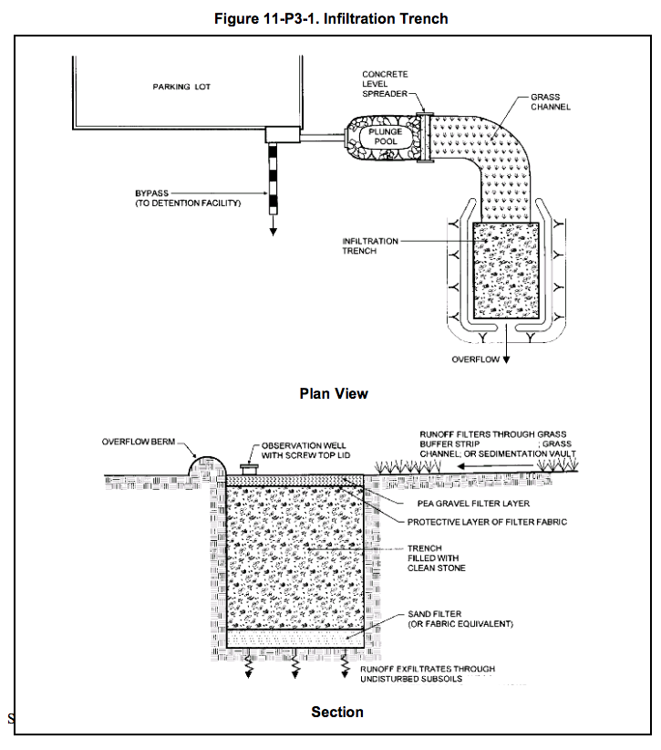
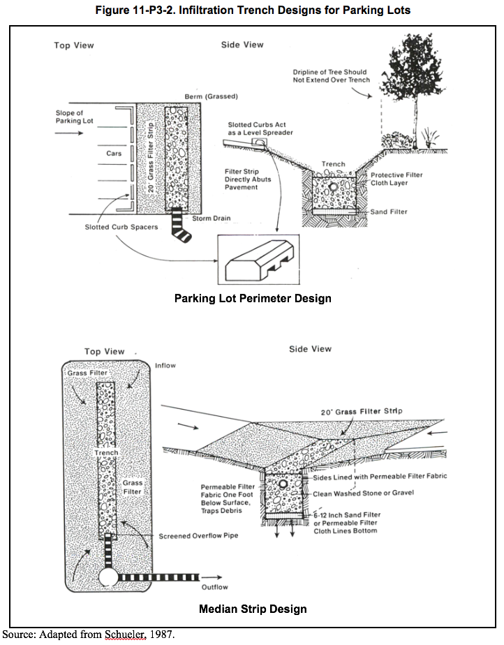
Two infiltration trench designs commonly used for parking lots are shown in Figure 11-P3-2.

Design Volume

• Infiltration trenches should be designed to infiltrate the entire water quality volume through the bottom of the trench (sides are not considered in sizing).
• Infiltration trenches should be designed as off-line practices.

Pretreatment

• Pretreatment should be provided to accommodate 25 percent of the water quality volume. Pretreatment generally consists of a sediment forebay or other device designed to capture coarse particulate pollutants, floatables, and oil and grease (if necessary). Pretreatment is required for soils with infiltration rates over 3.0 inches per hour.
• A vegetative buffer around the trench is recommended to intercept surface runoff and prolong the life of the structure.

Draining Time

• Infiltration trenches should be designed to completely drain the water quality volume into the soil within 48 to 72 hours after the storm event. Infiltration trenches should completely dewater between storms.
• A minimum draining time of 12 hours is recommended to ensure adequate pollutant removal.

Infiltration Rate

• A minimum field-measured soil infiltration rate of 0.3 inches per hour is recommended as a practical lower limit for the feasibility of infiltration practices. Lower infiltration rates may be acceptable provided that the water quality volume and drain time criteria can be met. Field-measured soil infiltration rates should not exceed 5.0 inches per hour.

Trench Surface Area and Depth

• The bottom area of the trench should be sized to allow for infiltration of the entire water quality volume within 48 hours. The trench bottom area can be calculated using the following equation (Metropolitan Council, 2001):

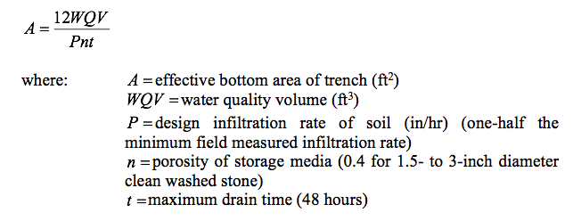
• The trench should be sized to hold the entire water quality volume. Therefore, the depth of the trench should be determined based on the water quality volume and the calculated effective bottom area.

Storage Media

• The trench should be filled with clean, washed aggregate with a diameter of 1.5 to 3 inches (porosity of 40 percent). The surface of the trench should be lined with permeable filter fabric and additional washed pea gravel or similar aggregate to improve sediment filtering in the top of the trench.
• The sides of the trench should be lined with filter fabric. The filter fabric should be compatible with the soil textures and application. The bottom of the trench can be lined with filter fabric or 6 to 12 inches of clean sand. Clean sand is preferred over filter fabric since clogging can occur at the filter fabric layer, and sand restricts downward flow less than fabric. Sand also encourages drainage and prevents compaction of the native soil while the stone aggregate is added.
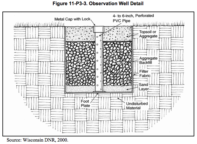
• An observation well should be installed along the trench centerline to monitor the water drainage in the system. The well should consist of a well-anchored, vertical perforated PVC pipe with a lockable aboveground cap (Figure 11-P3-3).

Conveyance

• Surface runoff exceeding the capacity of the trench should be conveyed in a stabilized channel if runoff velocities exceed erosive velocities (3.5 to 5.0 feet per second). If velocities do not exceed the non-erosive threshold, overflow may be accommodated by natural topography.
• Stormwater outfalls should be designed to convey the overflow associated with the 10-year design storm.

Winter Operation

• Infiltration trenches can be operated in the winter if the bottom of the trench is below the frost line.
• Freezing is less likely if a subsurface pipe carries runoff directly into the stone aggregate.
• Trenches covered with topsoil may not operate efficiently during the winter months because frozen soils tend to reduce infiltration.
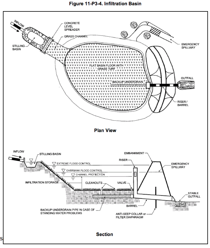
Infiltration Basin

Figure 11-P3-4 depicts a typical schematic design of an infiltration basin.

Design Volume

• Infiltration basins should be designed to infiltrate the entire water quality volume through the bottom of the basin.
• Infiltration basins should generally be designed as off-line practices, unless used as combined infiltration and flood control facilities or where retention of runoff from storms larger than the water quality design storm is required (e.g., discharges within 500 feet of tidal wetlands to meet runoff capture criterion).

Pretreatment

• Pretreatment should be provided to accommodate 25 percent of the water quality volume. Pretreatment generally consists of a sediment forebay or other device designed to capture coarse particulate pollutants, floatables, and oil and grease (if necessary). Pretreatment is required for soils with infiltration rates over 3.0 inches per hour.

Draining Time

• Infiltration basins should be designed to completely drain the water quality volume into the soil within 48 to 72 hours after the storm event. Infiltration basins should completely dewater between storms.
• A minimum draining time of 12 hours is recommended to ensure adequate pollutant removal.

Infiltration Rate

• A minimum field-measured soil infiltration rate of 0.3 inches per hour is recommended as a practical lower limit for the feasibility of infiltration practices. Lower infiltration rates may be acceptable provided that the water quality volume and drain time criteria can be met. Field-measured soil infiltration rates should not exceed 5.0 inches per hour.

Basin Dimensions and Configuration

  • The basin dimensions can be determined from the required storage volume and maximum depth of the basin. The required storage volume is equal to the water quality volume plus precipitation that falls within the basin during the water quality design storm:

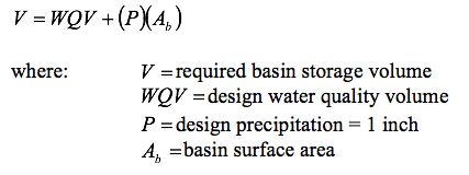
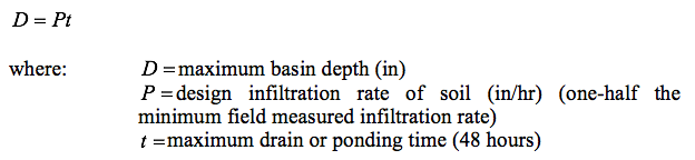
This equation conservatively assumes no infiltration during the water quality design storm. The depth of water in off-line infiltration basins should not exceed 3 feet for safety considerations. Larger depths may be required for combined infiltration/flood control basins. The maximum basin depth can be calculated from the following equation:

  • The length and width of the basin can be calculated from the water depth and required basin storage volume, as shown above.
  • The basin shape can be any configuration that blends with the surrounding landscape.
  • The floor of the basin should be graded as flat as possible for uniform ponding and infiltration.
  • The basin side slopes should be no steeper than 3:1 (horizontal:vertical). Flatter side slopes are preferred for vegetative stabilization, easier mowing and maintenance access, and safety.
  • Infiltration basins may be equipped with an underdrain system for dewatering when the systems become clogged.

Conveyance

  • Inlet channels to the basin should be stabilized to mitigate against erosive velocities. Riprap used for this purpose should be designed to spread flow uniformly over the basin floor.
  • A bypass flow path or pipe should be incorporated into the design of the basin to convey high flows around the basin via an upstream flow splitter.
  • Stormwater bypass conveyances should be designed to convey the overflow associated with the 10-year design storm.
  • Infiltration basins should be equipped with an emergency spillway capable of passing runoff from large storms without damage to the impoundment. The overflow should be conveyed in a stabilized channel if runoff velocities exceed erosive velocities (3.5 to 5.0 feet per second). If velocities do not exceed the non-erosive threshold, overflow may be accommodated by natural topography.

Vegetation

  • Vegetative buffers are recommended around the perimeter of the basin for erosion control and additional sediment filtering.
  • The bottom and side slopes of the basin should be planted with a dense stand of water-tolerant grass. Plant roots enhance the pore space and infiltration in the underlying soil. Use of low-maintenance, rapidly germinating grasses is recommended. Plants should be able to withstand prolonged periods of wet and dry conditions. Highly invasive plants are not recommended. Recommended plant species generally include those species appropriate for hydrologic zones 3 and 4 in Table A-1 of Appendix A. Loose stone, riprap, or other materials requiring hand removal of debris should not be used on the basin floor.

Construction

• Any stormwater treatment practices that create an embankment, including stormwater infiltration basins, are under the jurisdiction of the Dam Safety Section of the Connecticut DEP Inland Water Resources Division (IWRD) and should be constructed, inspected, and maintained in accordance with Connecticut General Statutes Sections 22a-401 through 22a-411, inclusive, and applicable DEP guidance.
• Proper construction of infiltration practices is critical to minimize the risk of premature failure.
• Infiltration practices should not be used as temporary sediment basins during construction.
• Infiltration practices should be constructed at or near the end of the development construction. The development plan sheets should list the proper construction sequence so that the infiltration structure is protected during construction.
• Before the development site is graded, the area of the infiltration practices should be roped off and flagged to prevent soil compaction by heavy equipment.
• Light earth-moving equipment (backhoes or wheel and ladder type trenchers) should be used to excavate infiltration practices. Heavy equipment can cause soil compaction and reduce infiltration capacity. Compaction of the infiltration area and surrounding soils during construction should be avoided.
• Smearing of soil at the interface of the basin or trench floor and sides should be avoided.
• The sides and bottom of an infiltration trench should be raked or scarified after the trench is excavated to restore infiltration rates.
• The floor of an infiltration basin should be raked or deep tilled after final grading to restore infiltration rates.
• Appropriate erosion and sediment controls should be utilized during construction, as well as immediately following construction to stabilize the soils in and around the basin.

Inspection and Maintenance

• Plans for infiltration practices should identify detailed inspection and maintenance requirements, inspection and maintenance schedules, and those parties responsible for maintenance.
• Pretreatment devices should be inspected and cleaned at least twice a year.
• For the first few months after construction infiltration trenches and basins should be inspected after every major storm. Inspections should focus on the duration of standing water in a basin or in the observation well of a trench after a storm. Ponding water after 48 hours indicates that the bottom of the infiltration structure may be clogged. If the bottom of the trench becomes clogged, all of the stone aggregate and filter fabric must be removed and replaced with new material. The bottom of the trench may need to be tilled to enhance infiltration. Water ponded at the surface of a trench may indicate only surface clogging.
• After the first few months of operation, maintenance schedules for infiltration practices should be based on field observations, although inspections should be performed at least twice per year. For infiltration trenches, observations should include checking for accumulated sediment, leaves and debris in the pretreatment device, clogging of inlet and outlet pipes, and ponded water inside and on the surface of the trench. For infiltration basins, observations should include measurement of differential accumulation of sediment, erosion of the basin floor, health of the basin vegetation, and condition of riprap.
• Grass clippings, leaves, and accumulated sediment should be removed routinely from the surface of infiltration trenches. The upper layer of stone and filter fabric may need to be replaced to repair surface clogging.
• Sediment should be removed from infiltration basins when the sediment is dry (visible cracks) and readily separates from the floor of the basin to minimize smearing the basin floor. The remaining soil should be tilled and revegetated.
• The grass in the basin, side slopes, and buffer areas should be mowed, and grass clippings and accumulated trash removed at least twice during the growing season. Mowing should not be performed when the ground is soft to avoid the creation of ruts and compaction, which can reduce infiltration.

Cost Considerations

Costs for implementation of infiltration practices are highly variable from site to site depending on soil conditions and the required pretreatment. Typical installation costs for infiltration trenches and basins are approximately $5.00 and $2.00 per cubic foot (adjusted for inflation) of stormwater treated (SWRPC, 1999), respectively. The cost per impervious acre treated varies by region and design variant. Infiltration basins are relatively cost-effective practices because little infrastructure is needed. Infiltration basins typically consume about 2 to 3 percent of the site draining to them. Maintenance costs for infiltration basins are estimated at 5 to 10 percent of construction costs, while maintenance costs for infiltration trenches are estimated at 20 percent of construction costs (EPA, 2002). Infiltration trenches are more expensive to construct than some other treatment practices in terms of cost per volume of stormwater treated. Because infiltration practices have high failure rates if improperly designed, constructed, and maintained, these practices may require frequent replacement, which would reduce their overall cost effectiveness.

References

Center for Watershed Protection (CWP). 2000. The Vermont Stormwater Management Handbook Technical Support Document – Public Review Draft.Prepared For Vermont Agency of Natural Resources.

Metropolitan Council. 2001. Minnesota Urban Small Sites BMP Manual: Stormwater Best Management Practices for Cold Climates.Prepared by Barr Engineering Company. St. Paul, Minnesota.

Wisconsin Department of Natural Resources. 2000. The Wisconsin Stormwater Manual: Infiltration Basins and Trenches.Publication Number G3691-3.

Schuler, T.R. 1987. Controlling Urban Runoff: A Practical Manual for Planning and Designing Urban BMPs.Metropolitan Washington Council of Governments. Washington, D.C.

Soil Conservation Service. 1986. Urban Hydrology for Small Watersheds, USDA Soil Conservation Service Technical Release No. 55. Washington, D.C.

Southeastern Wisconsin Regional Planning Commission (SWRPC). 1991. Costs of Urban Nonpoint Source Water Pollution Control Measures.Southeastern Wisconsin Regional Planning Commission. Waukesha, WI.

United States Environmental Protection Agency (EPA). 2002. National Menu of Best Management Practices for Stormwater Phase II.

URL: http://www.epa.gov/npdes/menuofbmps/menu.htm, Last Modified January 24, 2002.