4.1 Approaches that Optimize Conservation
4.1.1 Limits of Clearing and Grading
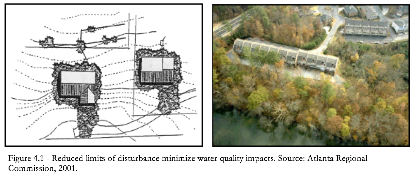
Perhaps the most potentially destructive stage in land development is the preparation of a site for building—clearing of vegetation and soil grading (Schueler, 1995). The limits of clearing and grading refer to the part of the site where development will occur. This includes all impervious areas such as roads, sidewalks, rooftops, as well as areas such as lawn and open drainage systems.
To minimize impacts, the area of development should be located in the least sensitive areas available. At a minimum, developers should avoid streams, floodplains, wetlands, and steep slopes. Where practicable, developers should also avoid soils with high infiltration rates as these will aid in reducing runoff volumes.
Advantages
- Preserves more undisturbed natural areas on a development site.
- Uses techniques to help protect natural conservation areas and other site features.
- Promotes evapotranspiration and infiltration to reduce need for treatment and peak volume control at end-of-pipe.
- Reduces generation of stormwater.
- Helps to demonstrate compliance with regulatory standards (e.g., freshwater wetlands, coastal resources, water quality, wildlife, local environmental protection, etc.) for avoidance and minimization as well as setbacks from sensitive features.
- Maintains predevelopment hydrology, natural character and aesthetic features that may increase market value.
- Promotes stable soils.
- May reduce landscaping costs.
Use
Establishing a limit of disturbance based on maximum disturbance zone radii/lengths.
These maximum distances should reflect reasonable construction techniques and equipment needs together with the physical situation of the development site such as slopes or soils. Limits of disturbance may vary by type of development, size of lot or site, and by the specific development feature involved.
Standards
Generally speaking, limits of disturbance need not comprise more than:
-
- Area of the building pad and utilities (e.g., onsite wastewater treatment systems and wells) plus 25 feet.
- Area of a roadbed and shoulder plus 9 feet. (This is not intended to limit lawn areas.)
4.1.2 Preserving Natural Areas
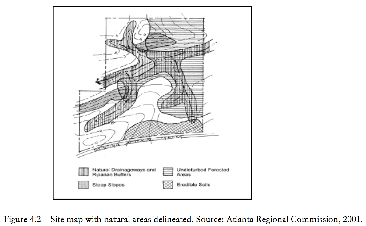
Natural areas include woodlands, riparian corridors, areas contiguous to wetlands and other hydrologically sensitive and naturally vegetated areas. To the extent practicable these areas should be preserved.
Natural areas can be one of the most important components within a development scheme, not only from a stormwater management perspective, but in reducing noise pollution and providing valuable wildlife habitat and scenic values. New development tends to fragment large tracts of undisturbed areas and displace plant and animal species; therefore it is essential to maintain these buffers in order to minimize impacts. Areas adjacent to waterbodies (both freshwater and coastal) are protected under state law and cannot be altered without a state agency permit.
Advantages
-
- Promotes evapotranspiration and infiltration to reduce need for treatment and peak volume control at end-of-pipe.
- Reduces generation of stormwater.
- Helps to demonstrate compliance with regulatory standards (e.g., freshwater wetlands, coastal resources, water quality, wildlife, local environmental protection, etc.) for avoidance and minimization as well as setbacks from sensitive features.
- Reduces safety and property-damage risks where flood hazard areas are incorporated into preservation.
- Maintains predevelopment hydrology, natural character and aesthetic features that may increase market value.
- Promotes stable soils.
- Establishes and maintains open space corridors.
Use
-
- Check all federal, state and local enforceable policy to ensure proper setbacks and identification of preservation areas. Identify areas for preservation through site analysis using maps and aerial or satellite photography or by conducting a site visit.
- Delineate areas for preservation via limits of disturbance before any clearing or construction begins and should be used to set the development envelope as well as guide site layout. Clearly mark areas for preservation on all construction and grading plans to ensure that equipment is kept out of these areas and that native vegetation is kept in an undisturbed state.
- Protect preservation areas in perpetuity by legally enforceable deed restrictions, conservation easements and maintenance agreements.
Special Considerations
Riparian Buffers
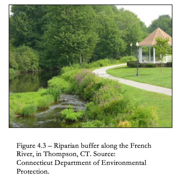
A riparian buffer is a special type of preserved area along a watercourse where development is restricted or prohibited. Buffers protect and physically separate a watercourse from development. Riparian buffers also provide stormwater control flood storage and habitat values. An example of a riparian buffer is shown in Figure 4.3. Wherever possible, riparian buffers should be sized to include the 100-year floodplain as well as steep banks and freshwater wetlands.
Riparian buffers consist of three zones (see Figure 4.4):
- The inner zone consists of the jurisdictional riverbank wetland and should be sized accordingly. In addition to runoff protection, this zone provides bank stabilization as well as shading and protection for the stream. This zone should also include wetlands and any critical habitats, and its width should be adjusted accordingly. Permits should be sought for activities in the inner zone. Generally speaking, structural best management practices (BMPs) are not allowed in the inner zone.
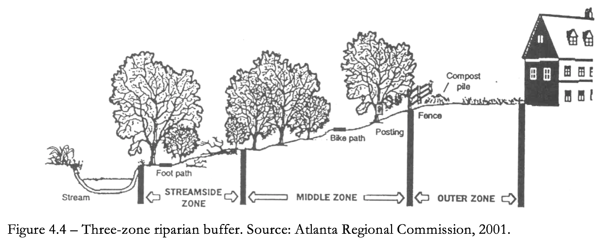
- The middle zone provides a transition between upland development and the inner zone and should consist of managed woodland that allows for infiltration and filtration of runoff. A 25-foot width is recommended for this zone at a minimum. Forested riparian buffers should be maintained and reforestation should be encouraged where no wooded buffer exists. Proper restoration should include all layers of the forest plant community, including understory, shrubs and groundcover, not just trees.
- An outer zone allows more clearing and acts as a further setback for impervious surfaces. It also functions to prevent encroachment and filter runoff. A 25-foot width is recommended for this zone.
Ideally, all three zones of the riparian buffer should remain in their natural state. However, some maintenance is periodically necessary, such as planting to minimize concentrated flow, the removal of exotic plant species when these species are detrimental to the vegetated buffer and the removal of diseased or damaged trees.
Floodplains
Floodplains are the low-lying flatlands that border streams and rivers. When a stream reaches its capacity and overflows its channel after storm events, the floodplain provides for storage and conveyance of these excess flows. In their natural state they reduce flood velocities and peak flow rates by the passage of flows through dense vegetation. Floodplains also play an important role in reducing sedimentation and filtering runoff, and provide habitat for both aquatic and terrestrial life. Development in floodplain areas can reduce the ability of the floodplain to convey stormwater, potentially causing safety problems or significant damage to the site in question, as well as to both upstream and downstream properties.
As such, floodplain areas should be avoided on a development site. Ideally, the entire 100-year floodplain at full buildout should be avoided for clearing or building activities, and should be preserved in a natural undisturbed state where possible. Maps of the 100-year floodplain can typically be obtained through the local review authority.
Standards
General
- No disturbance shall occur to preservation areas during project construction.
- Preserved areas shall be protected by limits of disturbance clearly shown on all construction drawings and clearly marked on site.
- Preservation areas shall be located within an acceptable conservation easement instrument that ensures perpetual protection of the proposed area. The easement must clearly specify how the natural area vegetation shall be managed and boundaries will be marked. [Note: managed turf (e.g., playgrounds, regularly maintained open areas) is not an acceptable form of vegetation management.]
- Preservation areas shall have a minimum contiguous area of 10,000 square feet or in the case of stream buffers must maintain a 50-foot set back from the jurisdictional wetland edge along the entire length of stream through the property of concern. Areas of smaller size may be incorporated for disconnection of impervious surface, but will be considered as open space in good condition.
- Incorporate level spreaders or other dispersion devices, where practicable, to ensure sheet flow. See Figure 4.5, which depicts a level spreader. (Please note that the level spreader shown here is for dispersion of low flows only.
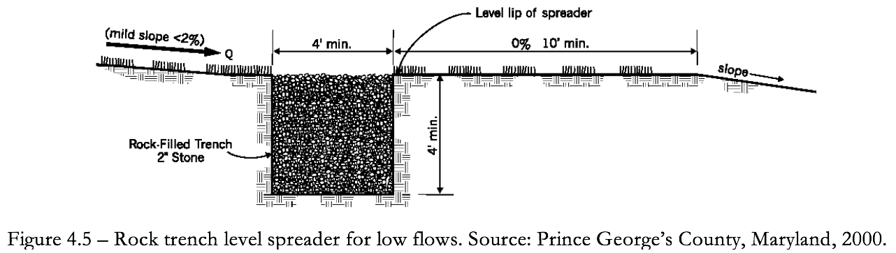
- Include bypass mechanisms for higher flow events to prevent erosion or damage to a buffer or undisturbed natural area.
- Consider incorporating constructed berms around natural depressions and below undisturbed vegetated areas to provide for additional runoff storage and infiltration. Proper use of berms is discussed in the section entitled vegetated filter strips.
- Where no berms are provided in Hydrologic Soil Group (HSG) type A and B soils, buffers may be used to attenuate and treat flows up to the water quality volume (i.e., volume equal to one inch over the impervious surface) in the following ratios:
- Land cover in buffers will be assumed to be woods in good condition (i.e., Curve number (CN) equal to 32 in type A soil and 55 in type B soil). Type C and D may not be used for this purpose as woods on these soil types cannot abstract the depth of rainfall associated with one inch of runoff from the impervious surface.
- Runoff must enter the buffer as overland sheet flow. The average contributing slope should be no less than 1% and no more 3%. Maximum average slope may be increased to 5% if a flow spreader is installed across the entire contributing length followed by a flat (i.e., 0% slope) 10-foot shelf across the length.
Streambank Areas
The minimum undisturbed buffer width should be at least the wetland jurisdictional setback plus 50 feet.
Maintenance
Except for routine debris removal, buffers shall remain in a natural and unmanaged condition.
4.2 Approaches that Mimic Natural Water Balance
LID controls mimic natural predevelopment hydrology in order to retain and attenuate stormwater runoff in upland areas. This reduces the amount of stormwater and intensity of flow at points of discharge. Flow attenuation prevents physical damage to waterways and reduces nonpoint source pollution. The remainder of Section 4.2 discusses mimic natural water balance as a LID control.
Advantages
- Decreased need for constructed BMPs.
- Maintain predevelopment hydrology and thus reduces generation of stormwater and associated pollution.
- Encourage groundwater recharge.
Use
Mimicking predevelopment site hydrology involves a process of comparing and evaluating pre- and postdevelopment conditions that takes place in all stages of site planning. There are many methods of hydrologic analysis. This section of the manual relies on the use of the USDA-SCS Technical Release-55 (TR-55), entitled Urban Hydrology for Small Watersheds (1986).
Time of Concentration and Time of Travel
TR-55 focuses on the time of concentration (Tc) as a primary influence in the shape and peak of runoff hydrographs. TR-55 defines time of concentration as the "time for runoff to travel from the hydraulically most distant point of the watershed to a point of interest within the watershed."
Tc is calculated as follows:
Tc = Tt(1) + Tt(2) + … Tt(m)
Where:
Tt (travel time) = time it takes runoff to move across a segment of the watershed.
m = total number of travel segments in a watershed
Tt is mathematically defined by TR-55 as being directly influenced by two factors velocity of runoff (V) and length of runoff flow path (L). Velocity is further defined as a function of slope (s) and surface roughness (i.e., Manning's roughness coefficient for sheet flow) (n).
Tt is calculated as follows:
L
Tt = 3600 V
Where:
Tt = travel time in hours
L = flow length in feet
V = average velocity in feet per second
3600 = conversion factor for seconds to hours
Total Volume and Peak Discharge
TR-55 also notes that total runoff volume (Q) and peak runoff discharge (qp) tend to increase as a result of urbanization. Peak discharge is defined as a factor of Q and can be calculated using as follows:
qp = qu Am Q Fp
Where:
qp = peak discharge in cubic feet per second
qu = unit peak discharge
Am = drainage area in square miles
Q = runoff in inches
Fp = pond and swamp adjustment factor
Q is derived as a factor of initial abstraction (Ia) and retention (S) and is calculated as follows:
Q = (P - Ia)2
(P - Ia) + S
Where:
Q = runoff in inches
P = rainfall in inches
S = retention
Ia = initial abstraction
Initial abstraction is a measure of rainfall held in surface depressions, interception by vegetation, evapotranspiration and infiltration prior to the occurrence of runoff and is calculated as follows:
Ia = 0.02 S
Where:
Ia = initial abstraction
S = retention
Retention is a measure of total capacity for rainwater storage in a watershed during a rain event. In small agricultural watersheds retention is typically about 5 times greater than initial abstraction.
Retention is calculated as follows:
S = 1000 - 10
CN
Where:
S = retention
CN = curve number
Curve number is a coefficient ranging from 0 - 100, which is used to represent the conversion of rainfall to runoff. For example, an impervious surface such as concrete has a CN of 98, which is analogous to representing that 98% of rain that falls on concrete runs off.
Identifying Hydrologic Benefits
All nonstructural and distributed BMPs have one or more hydrologic benefits in relationship to TR-55. Table 4.2) summarizes key hydrologic benefits of nonstructural and distributed BMPs recommended in this manual.
Table 4.2
Hydrologic Benefits of
Nonstructural and Distributed Techniques and Controls
| Techniques & Controls | Decrease Curve Number | Reduce Slope | Lengthen Flow Path | Increase Roughness | Increase Initial Abstraction | Increase Total Retention |
| Reduce Limits of Clearing and Grading |
•a |
Οb |
• |
• |
||
| Preserve Natural Features |
• |
• |
• |
• |
||
| Avoid Long, Steep Slopes |
• |
Ο |
• |
|||
| Avoid Erodible Soils |
• |
• |
||||
| Avoid Porous Soils | Ο |
• |
• |
|||
| Minimize Roadways |
• |
Ο |
• |
• |
||
| Minimize Buildings |
• |
• |
• |
• |
||
| Minimize Parking |
• |
• |
• |
• |
||
| Disconnect Impervious Area |
• |
Ο | Ο |
• |
||
| Buffers and Undisturbed Areas |
• |
• |
• |
• |
• |
|
| Infiltration Swales |
• |
Ο | Ο |
• |
• |
• |
| Vegetative Filter Strips |
• |
• |
• |
• |
||
| Bioretention |
• |
• |
• |
|||
| Nonstructural Conveyances |
• |
Ο |
• |
• |
||
| Drain Rooftop Runoff to Pervious Areas |
• |
• |
• |
|||
| Rain Barrels and Cisterns |
• |
• |
||||
| Dry Wells |
• |
• |
||||
| Green Roofs and Walls |
• |
• |
Notes
a Benefit always occurs.
b Benefit occurs sometimes.
Standards
Time of Concentration
The postdevelopment time of concentration (Tc) should approximate the predevelopment Tc.
Travel Time
The travel time (Tt) throughout individual lots and areas should be approximately constant.
Flow Velocity
Flow velocity in areas that are graded to natural drainage patterns should be kept as low as possible to avoid soil erosion.
Flows can be disbursed by installing a level spreader along the upland ledge of the natural drainage way buffer, and creating a flat grassy area about 30 feet wide on the upland side of the buffer where runoff can spread out. This grassy area can be incorporated into the buffer itself.
4.3.1 Roadways
- Reduces the amount of impervious cover and associated runoff and pollutants generated.
- Reduces the costs associated with road construction and maintenance.
 Use
Examine local ordinances and other requirements to determine standards and degree of flexibility available. Communities may have specific standards for setbacks and frontages or criteria for cul-de-sacs and other alternative turnarounds.
Reduce Roadway Lengths and Widths
Use
Examine local ordinances and other requirements to determine standards and degree of flexibility available. Communities may have specific standards for setbacks and frontages or criteria for cul-de-sacs and other alternative turnarounds.
Reduce Roadway Lengths and Widths
- Consider site and road layouts that reduce overall street length.
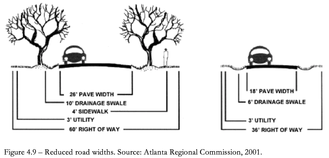
- Minimize street width by using narrower street designs as appropriate. Issues to consider include design speed, number of average daily trips (ADT), peak usage, need for on-street parking, sidewalks, design speed and right of way (see Table 4.3).
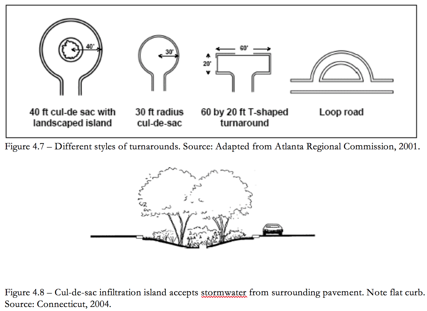
- Consider types of vehicles that may need to access a street. Sufficient turnaround area is a significant factor to consider in the design of cul-de-sacs. Fire trucks, service vehicles and school buses are often cited as needing large turning radii. However, some fire trucks are designed for smaller turning radii. In addition, many newer large service vehicles are designed with a tri-axle (requiring a smaller turning radius) and school buses usually do not enter individual cul-de-sacs.
- Minimize pavement at end-of-street turnarounds. Incorporate landscaped areas and consider alternatives to cul-de-sacs wherever practicable.
Table 4.3
Roadway Design Standards for Five Street Types
| Design Factor | Access | Local | Collector | Arterial |
| ADT | 0 – 500 | 500 – 5,000 | 2,500 – 10,000 | 7,500 – 20,000+ |
| Number of Lanes | 2 | 2 | 2 | 2 – 4 |
| Turn lanes | None | None | Left (when needed) | Left and Right (when needed) |
| Lane Width (feet) | 9 – 10 | 10 – 11 | 10 – 12 | 11 – 12 |
| On-Street Parking (feet) | None | 7 (parallel) | 8 (parallel) 16 – 18 (angle) | None except for CBD |
| Drainage | Swale or curb/gutter | Swale or curb/gutter | Swale or curb/gutter | Swale or curb/gutter |
| Target Speed (MPH) | 15 – 20 | 25 | 25 – 35 | 30 – 45 |
| Bicycle Lanes | None | Shared | Shared or seperate | Yes |
| Sidewalks | None or one-side | Two side | Two side | One side |
| Frontage Lots | Yes (may be rear) | Yes | Yes | Some |
4.3.2 Buildings
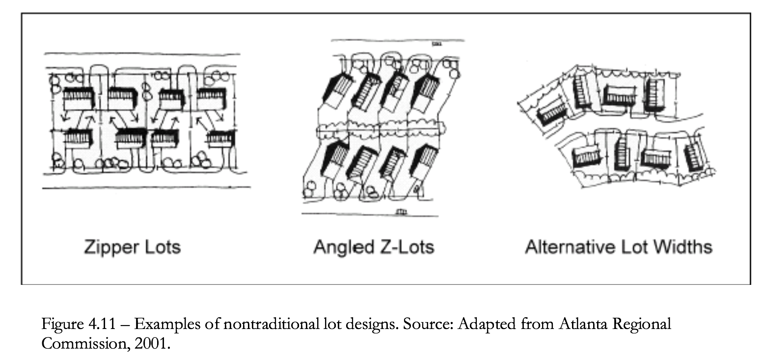
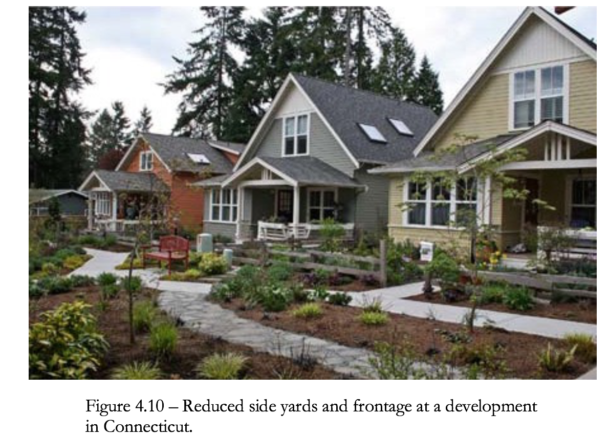 Flexible lot shapes and setback and frontage distances allow site designers to create attractive and unique lots that provide homeowners with enough space while allowing for the preservation of natural areas in a residential subdivision. Figure 4.11 illustrates various nontraditional lot designs.
 Use
Use smaller front and side setbacks and narrower frontages to reduce total road length and driveway lengths.
Reduce building and home front and side setbacks to allow for narrow frontages.
Consider narrower frontages.
Use
Use smaller front and side setbacks and narrower frontages to reduce total road length and driveway lengths.
Reduce building and home front and side setbacks to allow for narrow frontages.
Consider narrower frontages.
- Consider alternative build styles that reduce ratio of footprint to floor area.
- Review local regulations. Communities may have specific design criteria for setbacks and frontages.
- Minimize setbacks and lot frontages.
- Where practicable, reduce building setbacks to 20 - 30 feet and driveway widths to 18 feet.
- Where practicable, reduce frontages to 60 feet.
4.3.3 Parking Footprints
- Reduces the amount of impervious cover and associated runoff and pollutants generated.
- Many parking lot designs result in far more spaces than actually required. This problem is exacerbated by a common practice of setting parking ratios to accommodate the highest hourly parking during the peak season. By determining average parking demand instead, a lower maximum number of parking spaces can be set to accommodate most of the demand.
- If no local standards require a minimum number of spaces, apply the standards in Table 4.4 as a maximum number of spaces.
Table 4.4
Recommended Maximum Number of Parking Spaces for Certain Land Uses
| Land Use | Maximum Parking Spaces |
| Single Family House | 2 per DUa |
| Shopping Center | 5 per 1000 ft2 GFAb |
| Convenience Store | 3.3 per 1000 ft2 GFA |
| Industrial | 1 per 1000 ft2 GFA |
| Medical Dental | 5.7 per 1000 ft2 GFA |
 Another technique to reduce the parking footprint is to minimize the dimensions of the parking spaces. This can be accomplished by reducing both the length and width of the parking stall.
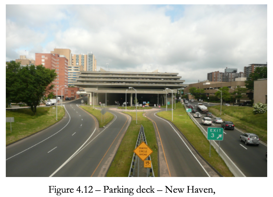
Use Parking Decks
Structured parking decks can significantly reduce the overall parking footprint by minimizing surface parking. Figure 4.12 shows a parking deck used for a commercial development.
Encourage Shared Parking
Shared parking in mixed-use areas and structured parking are techniques that can further reduce the conversion of land to impervious cover. For developments and blocks with a mix of land uses, perform a shared parking analysis in order to determine the peak demand for spaces for all uses rather than calculating each separately. Often mixed uses may be complimentary with regards to parking. For example, the peak demand for office buildings occurs during the period of minimal demand for residential buildings. The Urban Land Institute publication Shared Parking, Second Edition, 2005 provides a detailed methodology in order to determine the peak hour of parking demand and the overall number of spaces required for a mixed use development. This may reduce the number of spaces required by up to 20 percent.
Another technique to reduce the parking footprint is to minimize the dimensions of the parking spaces. This can be accomplished by reducing both the length and width of the parking stall.
Use Parking Decks
Structured parking decks can significantly reduce the overall parking footprint by minimizing surface parking. Figure 4.12 shows a parking deck used for a commercial development.
Encourage Shared Parking
Shared parking in mixed-use areas and structured parking are techniques that can further reduce the conversion of land to impervious cover. For developments and blocks with a mix of land uses, perform a shared parking analysis in order to determine the peak demand for spaces for all uses rather than calculating each separately. Often mixed uses may be complimentary with regards to parking. For example, the peak demand for office buildings occurs during the period of minimal demand for residential buildings. The Urban Land Institute publication Shared Parking, Second Edition, 2005 provides a detailed methodology in order to determine the peak hour of parking demand and the overall number of spaces required for a mixed use development. This may reduce the number of spaces required by up to 20 percent.4.3.4 Parking Lot Islands
- Reduces the amount of impervious cover and associated runoff and pollutants generated.
- Provides an opportunity for the siting of structural control facilities.
- Trees in parking lots provide shading for cars and are more visually appealing.
- Break up expanses of parking with landscaped islands, which include shade trees and shrubs.
- Fewer large islands will sustain healthy trees better than more numerous very small islands.
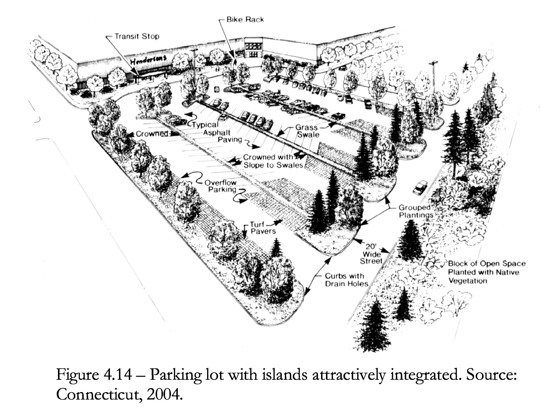 Standards
Parking lot islands should:
Standards
Parking lot islands should:
- Be at least 8 feet wide.
- Be constructed with sub-surface drainage.
- Incorporate compaction resistant soil.
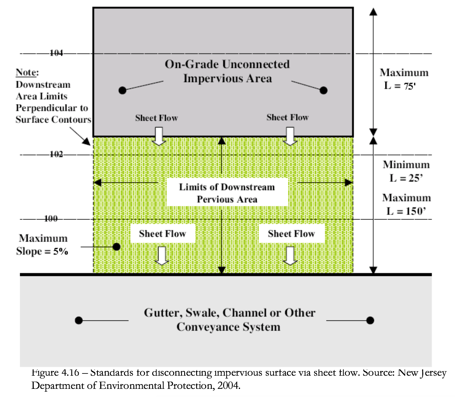
4.3.6 Disconnecting Impervious Areas
Table 4.5
Ratio of Open Space: Pervious Area Necessary to Attenuate Surface Runoff for Runoff Between 0.5 and 1.0 Inchesa, b
| HSG Soil Type | ||||
| Runoff (inches) | A | B | C | D |
| 1.0 | 1:2 | 4:1 | N/A | N/A |
| 0.9 | 1:3 | 2:1 | N/A | N/A |
| 0.8 | 1:4 | 1:1 | N/A | N/A |
| 0.7 | 1:8 | 1:2 | N/A | N/A |
| 0.6 | 1:8 | 1:3 | 2:1 | N/A |
| 0.5 | 1:8 | 1:6 | 1:1 | N/A |
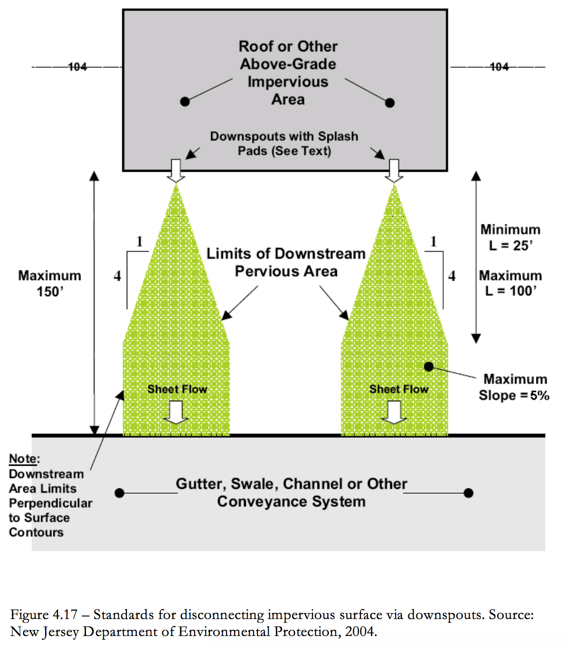 Downspouts
a) Downspout outfall expands in width at a rate of 1:4 for a maximum length of 100 feet and a minimum length of 25 feet.
b) No downspout may drain more than 600 square feet of roof.
c) Downspouts should be at least 10 feet away from the nearest impervious surface (e.g., driveways) to discourage reconnections to those surfaces.
d) Downspouts must be equipped with splash pads, level spreaders, or dispersion trenches that reduce flow velocity and induce sheet flow in the downstream pervious area.
Downspouts
a) Downspout outfall expands in width at a rate of 1:4 for a maximum length of 100 feet and a minimum length of 25 feet.
b) No downspout may drain more than 600 square feet of roof.
c) Downspouts should be at least 10 feet away from the nearest impervious surface (e.g., driveways) to discourage reconnections to those surfaces.
d) Downspouts must be equipped with splash pads, level spreaders, or dispersion trenches that reduce flow velocity and induce sheet flow in the downstream pervious area.4.4 Integrated Management Practices at the Source
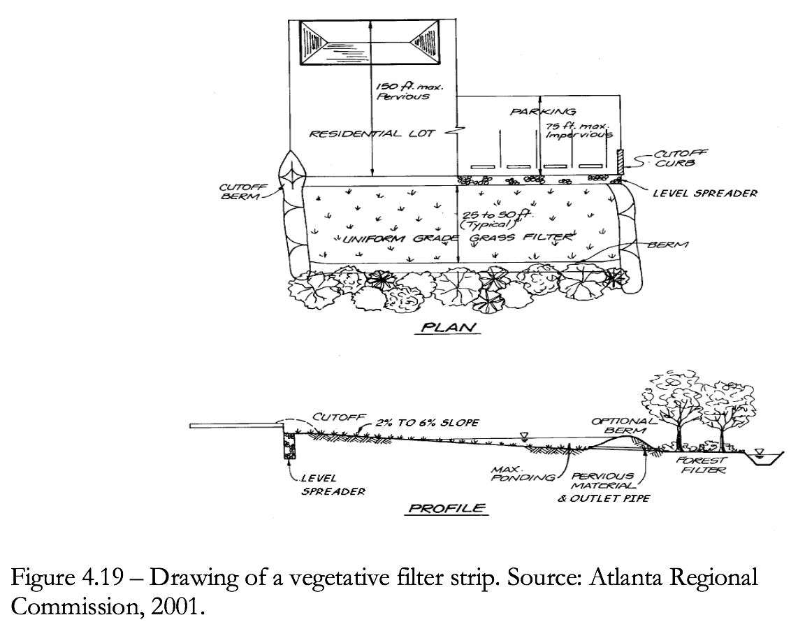
4.4.1 Vegetated Filter Strips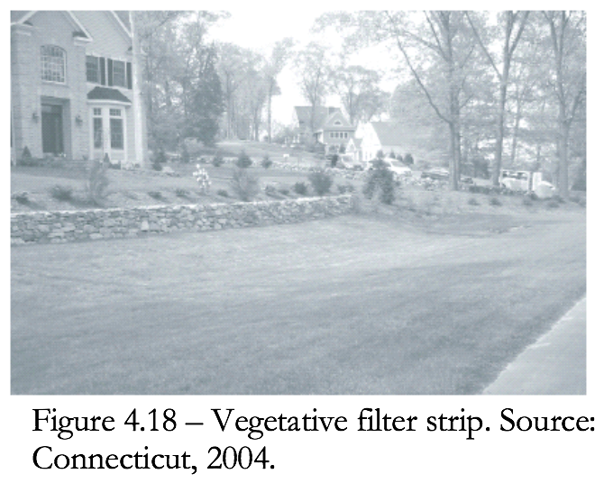
A vegetated filter strip is an undisturbed densely vegetated area (e.g., well-tended lawn) contiguous with a developed area. These filter strips are most often located between a water resource and the developed portion of a site (see Figure 4.18).
Advantages
Filter strips serve to improve runoff water quality, add or maintain wildlife habitat, and provide a screening effect for homeowners. This type of BMP is best suited for complementing other structural methods utilized on-site for stormwater management.
Use
Filter strips can be composed of an undisturbed-forested area or created from disturbed land by proper seeding and plantings. Where grass is being used, the most effective pollutant removal filter strip is composed of dense grassy vegetation that is properly maintained
Channelization of runoff within the filter strip significantly reduces the amount of infiltration and subsequent pollutant removal. Filter strips must have a level-spreading device incorporated into the design. Caution must be used when installing level spreaders to ensure long-term even flow and distribution of runoff to the filter strip. See Figure 4.5 for an example of a level spreader. Low volume pedestrian pathways may be constructed through a buffer strip, provided they are no greater than 5 feet wide and take a winding course to reduce the potential for channelized runoff flow. Pesticides should not be applied in these areas, although minimal, fertilizer use is acceptable to help seeded areas become more quickly established. Incorporating organic material, such as mulch, into the topsoil is encouraged to promote better filter strip performance.
Soils with a high content of organic material will attenuate greater amounts of pollutants from stormwater runoff.
Standards
Chapter 11 of the current Stormwater Quality Manual includes specific design standards and considerations for vegetative filter strips, which should be followed when implementing these BMPs.
4.4.2 Natural and Vegetated Drainage Ways
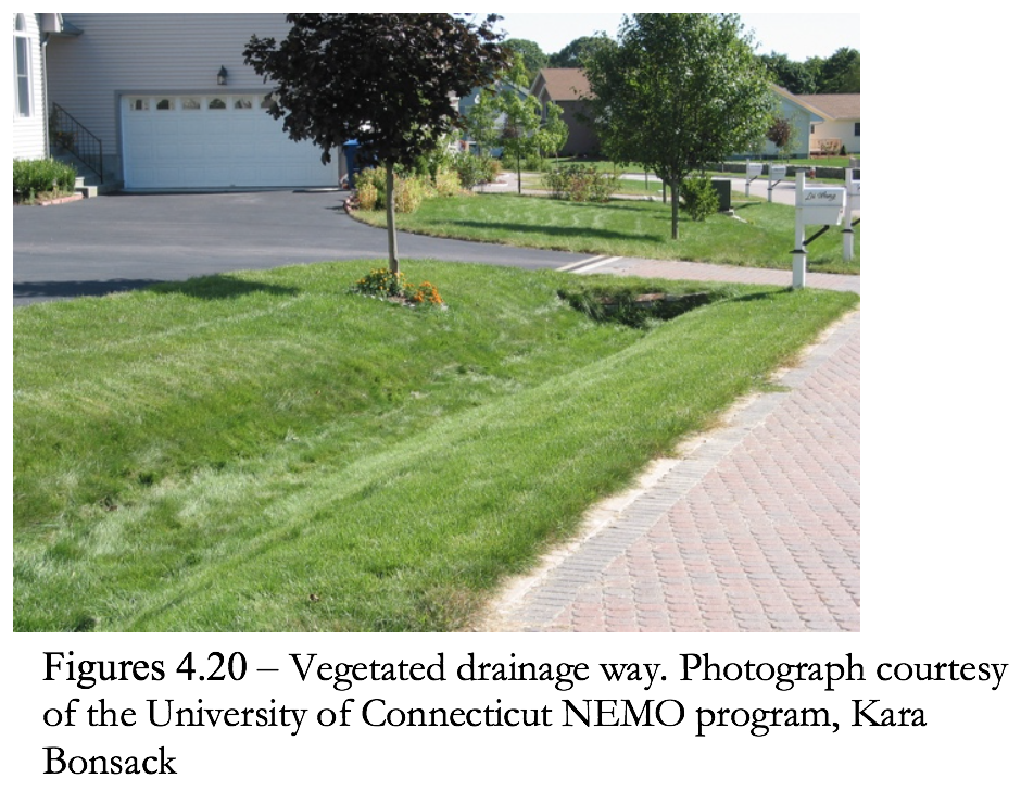
Structural drainage systems and storm sewers are designed to be hydraulically efficient for removing stormwater from a site. However, in doing so these systems tend to increase peak runoff discharges, flow velocities and the delivery of pollutants to downstream waters. An alternative is the use of natural drainage ways such as grass natural drainage systems (see Figure 4.20).
The use of natural open channels allows for more storage of stormwater flows on-site, lower stormwater peak flows, a reduction in erosive runoff velocities, infiltration of a portion of the runoff volume, and the capture and treatment of stormwater pollutants.
Advantages
• Reduces or eliminates the cost of constructing storm sewers or other conveyances, and may reduce the need for land disturbance and grading.
• Increases travel times and lower peak discharges.
• Can be combined with buffer systems to enhance stormwater filtration and infiltration.
Use
a) Use vegetated open channels in the street right-of-way to convey and treat stormwater runoff from roadways, particularly for low-density development and residential subdivisions where density, topography, soils, slope, and safety issues permit.
b) Use vegetated open channels in place of curb and gutter to convey and treat stormwater runoff.
c) Design drainage systems and open channels to:
i. Increase surface roughness to retard velocity.
ii. Include wide and flat channels to reduce velocity of flow and encourage sheet flow if possible.
iii. Increase channel flow path to increase time of concentration and travel time.
Standards
Chapter 11 of the current Stormwater Quality Manual includes specific design standards and considerations for grass drainage channels, which should be followed when implementing these BMPs.
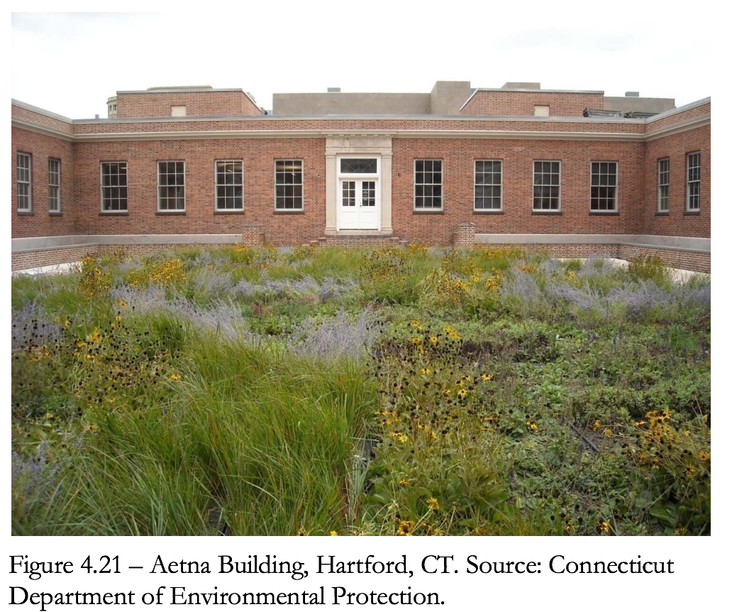
4.4.3 Green Roofs and Facades
Rooftop runoff management structures are modifications to conventional building design that retard runoff originating from roofs. The modifications include:
• Vegetated roof covers
• Roof gardens
• Vegetated building facades
• Roof ponding areas
Roofs are significant sources of concentrated runoff from developed sites. If runoff is controlled at the source, the size of other BMPs throughout the site can be minimal. Rooftop runoff management practices influence the runoff hydrograph in two ways:
• Intercept rainfall during the early part of a storm.
• Limit the maximum release rate.
In addition to achieving specific storm water runoff management objectives, rooftop runoff management can also be aesthetically and socially beneficial.
Advantages
• Rooftop runoff management techniques can be retrofitted to most conventionally constructed buildings.
• Reduces energy consumption for heating and cooling.
• Conserves space.
• Reduces wear on roofs caused by UV damage, wind, and extremes of temperature. Vegetative roof covers can reduce bare roof temperatures in summer by as much as 40 percent.
• Roof gardens, vegetated roof covers, and vegetated facades add aesthetic value to residential and commercial property that attract songbirds, bees, and butterflies.
• Benefit water quality by reducing the acidity of runoff and trapping airborne particulates.
• May reduce the size of onsite runoff attenuation BMPs.
Use
a) Use vegetative roofs on residential, commercial and light industrial buildings.
b) Vegetative roof systems are most appropriate on roofs with slopes of 12:1 to 4:1.
c) Vegetative roofs may be used on flatter slopes if an underdrain is installed.
Design Variations
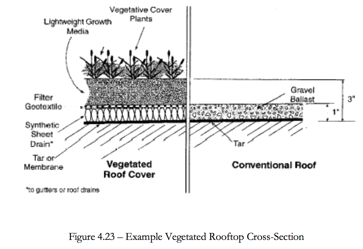
• Vegetated roof cover – Vegetated roof covers, also called green roofs and extensive roof gardens, involve blanketing roofs with a veneer of living vegetation. Vegetative roof covers are particularly effective when applied to extensive roofs, such as those that typify commercial and institutional buildings. The filtering effect of vegetated roof covers results in a roof discharge that is free of leaves and roof litter. Therefore, it is recommended where roof runoff will be directed to infiltration devices (see Standards for Infiltration Practices and Dry Wells.)
Because of recent advances in synthetic drainage materials, vegetated covers now are feasible on most conventional flat roofs. An efficient drainage layer is placed between the growth media and the roof surface. This layer rapidly conveys water off of the roof surface and prevents water from “lying” on the roof. In fact, vegetated roof covers can be expected to protect roof materials and prolong their life.
If materials are selected carefully to reduce the weight of the system, vegetated roof covers generally can be created on existing flat roofs without additional structural support. Drainage nets or sheet drains constructed from lightweight synthetic materials can be used as underlayments to carry away water and prevent ponding. The total load of a fully vegetated and saturated roof cover system can be less than the design load computed for gravel ballast on conventional tar roofs.
Although vegetative roof covers are most effective during the growing season, they also are beneficial during the winter months as additional insulation if the vegetative matter from the dead or dormant plants is left in place and intact.
• Roof Gardens – Vegetated roof covers blanket an entire roof area and, although presenting an attractive vista, generally are not intended to accommodate routine traffic by people. Roof gardens, on the other hand, are landscaped environments, which may include planters and potted shrubs and trees. Roof gardens can be tailor-made natural areas, designed for outdoor recreation, and perched above congested city streets. Because of the special requirements for access, structural support, and drainage, roof gardens are found most frequently in new construction.
Roof gardens generally are designed to achieve specific architectural objectives. The load and hydraulic requirements for roof gardens will vary according to the intended use of the space. Intensive roof gardens typically include design elements such as planters filled with topsoil, decorative gravel or stone, and containers for trees and shrubs. Complete designs also may detain runoff ponding in the form of water gardens or storage in gravel beds. A wide range of hydrologic principles may be exploited to achieve storm water management objectives, including runoff peak attenuation and runoff volume control.
• Vegetated Building Facades – Vegetated facades provide many of the same benefits as vegetated roof covers and roof gardens, including the interception of precipitation and the retardation of runoff. However, their effectiveness is limited to small rainfall events.
Vertical facades and walls of houses can be covered with the foliage of self-climbing plants that are rooted in the ground and reach heights in excess of 80 feet. Vines can be evergreen or prolific deciduous flowering plants. As for roof gardens, the designer must be judicial in selecting plant species that will prosper in the constructed environment. Planters and trellises can be installed so that vegetation can be placed strategically.
• Roof Ponding – Roof ponding is applicable where the increased load of impounded water on a roof will not increase the building costs significantly or require extensive reinforcement. Roof ponding generally is not viable for large-area commercial buildings where clear spans are required. Special consideration must be given to ensuring that the roof will remain watertight under a range of adverse weather conditions. Low-cost plastic membranes can be used to construct an impermeable lining for the containment area.
Flat roofs can be converted to ponding areas by restricting the flow to downspouts. Even small ponding depths of 1 or 2 inches can attenuate storm water-runoff peaks effectively for most storms.
Design Considerations
Rooftop measures are primarily peak runoff attenuation measures. The methods for evaluating the peak attenuation properties of these measures are based on approaches used for other peak runoff attenuation BMPs. The emphasis of the design should be promoting rapid roof drainage and minimizing the weight of the system. By using appropriate materials, the total weight of fully saturated vegetated roof covers can readily be maintained below 20 pounds per square foot (psf). Because of the many factors that may influence the design of vegetated roof covers, it is advisable to obtain the services of installers that specialize in this area.
Rainfall retention properties are related to field capacity and wilting point. Appropriate media for this application should be capable of retaining water at the rate of 40 percent by weight, or greater. The media must be uniformly screened and blended to achieve its rainfall retention potential. During the early phases of a storm, the media and root systems of the cover will intercept and retain most of the rainfall, up to the retention capacity. For instance, 3-inch cover with 40 percent retention potential will effectively control the first 1.2 inches of rainfall. Although some water will percolate through the cover during this period, this quantity generally will be negligible compared to the direct runoff rate without the cover in place.
Once the field capacity of the cover is attained, water will drain freely through the media at a rate that is approximately equal to the saturated hydraulic conductivity for the media. Through the selection of the media, the maximum release rate from the roof can be controlled. The media is a mechanism for “buffering” or attenuating the peak runoff rates from roofed areas. Rooftop runoff management measures generally are more effective in controlling storms that generate 1 inch or less of runoff (i.e., 1.2-inch storm). However, because storms of this size constitute the majority of rainfall events, rooftop runoff measures can be important in planning for comprehensive storm water management. These measures are particularly useful when linked to groundwater recharge BMPs such as infiltration trenches, dry wells, and permeable pavements. By retaining rainfall for evaporation or plant transpiration, some rooftop runoff management measures, such as vegetated roof covers, can also achieve significant reductions in total annual runoff. This attenuation of runoff peaks from larger storms should be taken into account when sizing related runoff peak attenuation at the site.
By using specific information about the hydraulic properties of the cover media, the effect of the roof cover system on the runoff hydrograph can be approximated with numerical modeling techniques. As appropriate, the predicted hydrographs can be added into site-wide runoff models to evaluate the effect of the vegetative roof covers on site runoff. The hydraulic analysis of roof covers will require the services of a professional engineer who is experienced with drainage design.
Impermeable Lining
a) In some instances, the impermeable lining can be the watertight tar surface, which is conventional for flat roof construction. However, where added protection is desired, a layer of plastic or rubber membrane can be installed immediately beneath the drainage net or sheet drain. This liner needs to be designed by a professional engineer to ensure proper function.
b) If membranes are used, their resistance to ultraviolet (UV) radiation, extremes of temperature, and puncture must be known. In most cases, covering the sealing material with a protective layer of gravel or geotextile is advisable.
Drainage
a) The drainage net or sheet drain is a continuous layer that underlies the entire cover system. A variety of lightweight, high-performance drainage products will function well in this environment. The product selected should be capable of conveying the discharge associated with the runoff peak attenuation storm without ponding water on top of the roof cover. When evaluating a drainage layer design, the roof topography should be evaluated to establish where the longest travel distances to a roof gutter, drain, or downspout occur. If flow converges near drains and gutters, the design unit-flow rate should be increased accordingly.
b) Drainage nets or sheet drains with transmissivities of 15 gallons per minute per foot, or larger, are recommended.
c) The drainage layer should be able to convey the design unit flow rate at the roof grade without water ponding on top of the cover media. For larger storms, direct roof runoff is permitted to occur. The design flow rates should be based on the largest runoff peak attenuation design storm considered in the design.
d) To prevent the growth media from penetrating and clogging the drainage layer and to prevent roots from penetrating the roof surface, a geotextile should be installed immediately over the drainage net or sheet drain. Many vendors will bond the geotextile to the upper surface of the drainage material.
e) Effective roof garden designs will ensure that all direct rainfall is cycled through one or more devices before being discharged to downspouts as runoff. For instance, rainfall collected on a raised tile patio can be directed to a media-filled planter where some water is retained in the root zone and some is detained and gradually discharged through an overflow to the downspout.
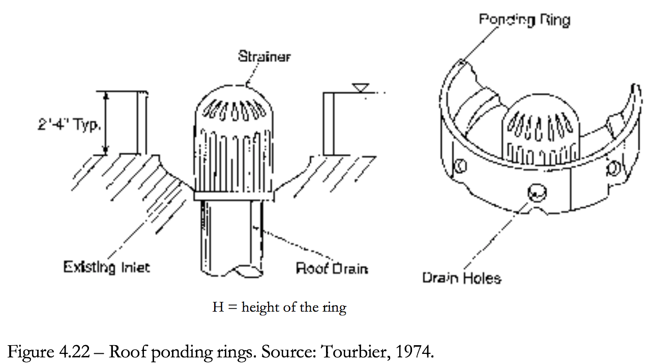
f) In the case of roof ponding, devices such as the one shown in Figure 4.22, are easily fabricated. However, some form of emergency overflow also is advisable. Emergency overflow can be as simple as a free overfall through a notch in the roof parapet wall.
g) In roof ponding systems, because the roof is impermeable, the runoff hydrograph is simply the rainfall distribution for the design storm multiplied by the area of the roof.
The depth to storage relationship can be computed from the topography of the roof. For perfectly flat roofs, the storage volume of a ponding level is equal to the roof area times the ponding level. The depth-discharge relationship in will be unique to the outlet device used. For simple ponding rings on flat roofs, the discharge rate will approximately equal:
q = 3.141 CD (d – H)3/2
Where:
q = outflow rate
C = discharge coefficient (Varies based on design) Typical: C = 3.0
D = diameter of the ring
d = depth of ponding
H = height of the ring
Roof Loading
The net weight of the fully vegetated roof cover should be compared against the design loads for the roof.
Lightweight Growth Media
a) The depth of the growth media should be kept as small as the cover vegetation will allow. Typically, a depth of 3 to 4 inches will be sufficient. Low-density substrate materials with good water-retention capacity should be specified. Examples are mixtures containing crushed pumice and terra cotta. Media that are appropriate for this application will retain 40 to 60 percent water by weight and have bulk dry densities of between 35 and 50 lb/cubic foot. Earth and topsoil are too heavy for most applications.
b) Hydrologic properties are specific to the growth medium. If the supplier does not provide information, prospective media should be laboratory tested to establish porosity, moisture content at field capacity, moisture content at the wilting point (nominally 0.33 bar), and saturated hydraulic conductivity.
Adapted Plants and Grasses
a) A limited number of plants can thrive in the roof environment where periodic rainfall alternates with periods that are hot and dry. Effective plant species must:
i. Tolerate mildly acidic conditions and poor soil;
ii. Prefer very-well-drained conditions and full sun;
iii. Tolerate dry soil;
iv. Be vigorous colonizers.
Both annual and perennial plants can be used. Dozens of species have been successfully field-tested. Among these, some species of sedum (Sedum) have been shown to be particularly well adapted. Other candidates include hardy species of sedge (Carex), fescue (Festuca), feather grass (Stipa), and yarrow (Achillea).
b) Vegetative roof covers may include provisions for occasional watering during extended dry periods. Conventional lawn sprinklers work well.
c) The key to developing an effective vegetated facade is selecting plants that are well adapted to the conditions in which they must grow. For instance, depending on the location, plants may encounter shade or full sun. Plants that will provide thick foliage should be selected. Some plants with good climbing and foliage characteristics are ivy (Hedera), honeysuckle (Loniciera), wisteria (Wisteria), Virginia creeper (Part henocissus), trumpet creeper (Campsis), and hardy cultivars of clematis (e.g., Cleinatis paniculata). Some of these plants will require a trellis or lattice to firmly support the vines.
Inspection and Maintenance
a) Plans for water quality swales should identify detailed inspection and maintenance requirements, inspection and maintenance schedules, and those parties responsible for maintenance.
b) All rooftop runoff management measures must be inspected and maintained periodically. Furthermore, the vegetative measures require the same normal care and maintenance that a planted area does. The maintenance includes attending to plant nutritional needs, irrigating as required during dry periods, and occasionally weeding.
c) The cost of maintenance can be significantly reduced by judiciously selecting hardy plants that will outcompete weeds.
d) In general, fertilizers must be applied periodically. Fertilizing usually is not a problem on flat or gently sloping roofs where access is unimpeded and fertilizers can be uniformly broadcast.
e) Properly designed vegetated roof covers should not be damaged by treading on the cover system.
f) When retrofitting existing roofs, preserve easy access to gutters, drains, spouts, and other components of the roof drainage system.
g) It is good practice to thoroughly inspect the roof drainage system quarterly. Foreign matter, including leaves and litter, should be removed.
Table 4.6
Typical Maintenance Activities for Rooftop Runoff Structures
| Activity | Schedule |
|
Quarterly |
|
As necessary |
|
As necessary |
|
As necessary |
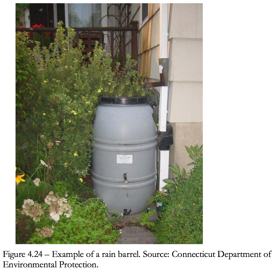
4.4.4 Rain Barrels and Cisterns
Rain barrels and cisterns are rainwater collection and storage devices (see Figure 4.24). They are generally low-cost and easily maintainable. They are applicable, for purposes of retrofit, to residential, commercial and industrial sites to manage rooftop runoff. Rain barrels and cisterns are not generally given stormwater management credit on new development.
Advantages
• Low cost.
• Applicable to a wide range of sites (e.g., residential, commercial industrial, etc.).
• Provide retention and detention of runoff from roofs.
• Can provide reuse of water for landscape irrigation.
Use
a) Use rain barrels and cisterns in commercial, industrial and domestic settings.
b) Incorporate rain barrels and cisterns when a building is being designed so that they can be blended into the landscape. They can also be retrofitted.
c) Size rain barrels and cisterns based on roof area. The required capacity of a rain barrel is a function of the rooftop surface evaporative water losses and initial abstraction.
Rain barrel volume can be determined by calculating the roof top water yield for any given rainfall, using Equation 10. A general rule of thumb to utilize in the sizing of rain barrels is that 1 inch of rainfall on a 1000-square-foot roof will yield approximately 600 gallons.
V = A2 x R x 0.90 x 7.5 gals/ft3
where:
V = volume of rain barrel (gallons)
A2 = surface area roof (square feet)
R = rainfall (feet)
0.9 = losses to system (no units)
7.5 = conversion factor (gallons per cubic foot)
Example: one 60-gallon barrel would provide runoff storage from a rooftop area of approximately 215 square feet for a 0.5 inch (0.042 ft.) of rainfall.
60 gallons = 215 ft.2 x 0.042 ft. x 0.90 x 7.5 gallons/ft.3
d) If collected water will be used as a drinking source, the system will generally require local authority review and approval.
e) Assure long-term function by establishing maintenance agreements.
Standards
Chapter 4 of the current Stormwater Quality Manual includes specific design standards and considerations for rain barrels and cisterns, which should be followed when implementing these BMPs.
4.4.5 Dry Wells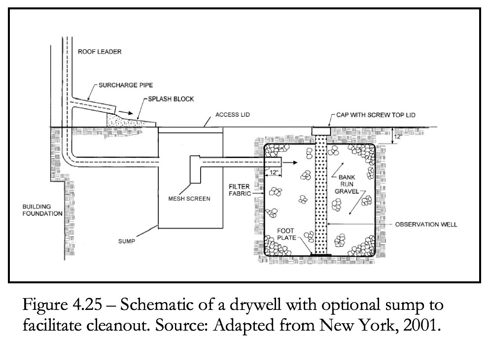
A dry well is a small, excavated pit, backfilled with stone aggregate. Dry wells function like infiltration systems to control roof runoff and are applicable for most types of buildings (see Figure 4.25).
Advantages
• Low cost.
• Applicable to a wide range of sites (e.g., residential, commercial industrial, etc.).
• Provides retention of runoff from roofs.
• Recharges groundwater.
• Reduces need for end-of-pipe treatment.
Use
a) Dry wells can be useful for disposing of roof runoff and reducing the overall runoff volume from a variety of building sites.
b) Infiltration of rooftop runoff from commercial or industrial buildings with pollution control, heating, cooling, or venting equipment may require UIC review and approval.
Standards
Chapter 4 and 11 of the current Stormwater Quality Manual include specific design standards and considerations for dry wells, which should be followed when implementing these BMPs.
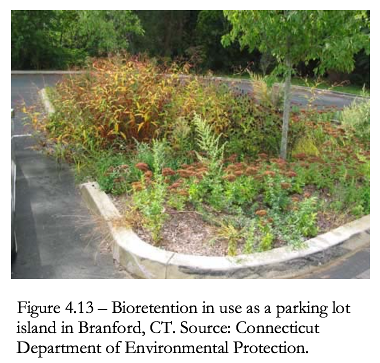
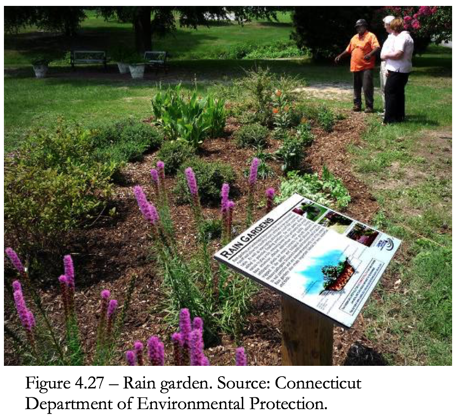
4.4.6 Bioretention and Rain Gardens
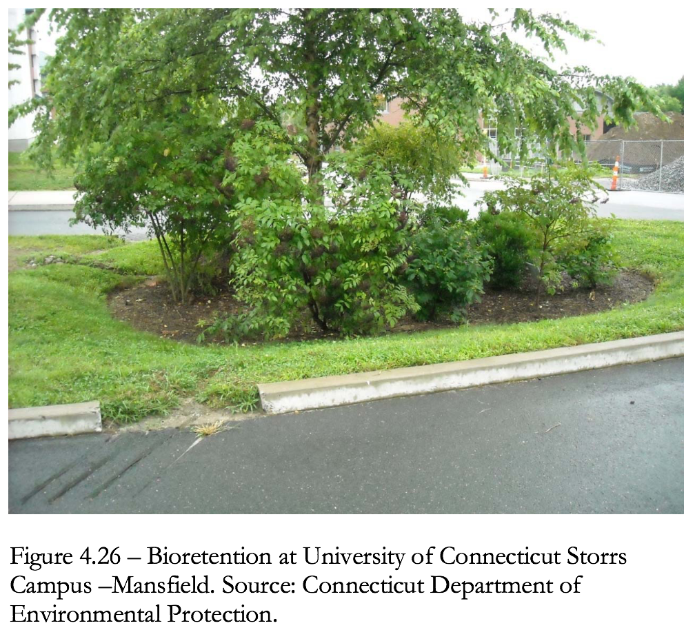 Bioretention and rain gardens are shallow landscaped depressions designed to manage and treat storm water runoff. Bioretention systems are a variation of a surface sand filter, where the sand filtration media is replaced with a planted soil bed designed to remove pollutants through physical and biological processes (EPA, 2002). The concept of bioretention originated with the Prince Gorge’s County, Maryland, Department of Environmental Resources in the early 1990s as an alternative to more traditional management practices. Storm water flows into the bioretention area, ponds on the surface, and gradually infiltrates into the soil bed. Treated water is allowed to infiltrate into the surrounding soils or is collected by an underdrain system and discharged to the storm drain system or receiving waters. Small-scale bioretention applications (i.e., residential yards, median strips, parking lot islands) are commonly referred to as rain gardens (Figure 4.27).
 Advantages
• Applicable to small drainage areas, storm water retrofits and highly developed sites.
• Can be applied to most sites due to relatively few constraints and many design variations (i.e., highly versatile).
• High solids, metals, and bacteria removal efficiency.
• Infiltrating bioretention can provide groundwater recharge.
• Helps to mimic predevelopment runoff conditions.
• Reduces need for end-of-pipe treatment.
Use
a) Bioretention may be used in a wide variety of settings including residential, commercial, and industrial areas.
b) May be decentralized (e.g., as rain gardens on individual lots) or centralized in common areas to manage multiple properties.
c) May be lined and underdrained; or designed to infiltrate and recharge groundwater.
Standards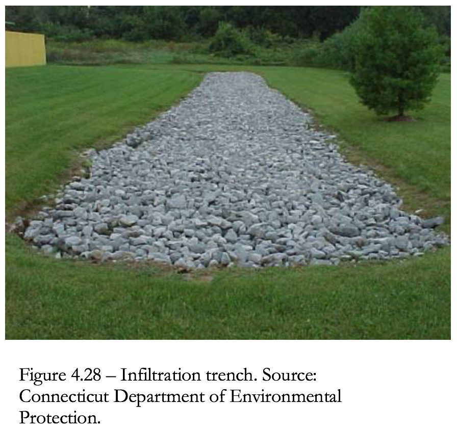
Chapter 4 and 11 of the current Stormwater Quality Manual include specific design standards and considerations for bioretention, which should be followed when implementing these BMPs.
4.4.7 Infiltration Trenches
An infiltration trench is an excavated trench that has been back-filled with stone to form a subsurface basin. Stormwater runoff is diverted into the trench and is stored until it can be infiltrated into the soil, unusually over a period of 1 – 2 days.
Advantages
• Applicable to small drainage areas, storm water retrofits and highly developed sites.
• High bacteria removal efficiency.
• Infiltration provides groundwater recharge.
• Helps to mimic predevelopment runoff conditions.
• Reduces need for end-of-pipe treatment.
Use
a) Infiltration may be useful for disposing of roof runoff (e.g., dry wells), or runoff from parking lots and roadways.
b) Infiltration trenches generally have a longer life cycle when hydrologically proceeded by pretreatment such as a vegetated filter strip.
c) Infiltration generally requires UIC review and approval.
Standards
Chapter 11 of the current Stormwater Quality Manual includes specific design standards and considerations for infiltration, which should be followed when implementing infiltration BMPs.
4.4.3 Green Roofs and Facades
Rooftop runoff management structures are modifications to conventional building design that retard runoff originating from roofs. The modifications include:
• Vegetated roof covers
• Roof gardens
• Vegetated building facades
• Roof ponding areas
Roofs are significant sources of concentrated runoff from developed sites. If runoff is controlled at the source, the size of other BMPs throughout the site can be minimal. Rooftop runoff management practices influence the runoff hydrograph in two ways:
• Intercept rainfall during the early part of a storm.
• Limit the maximum release rate.
In addition to achieving specific storm water runoff management objectives, rooftop runoff management can also be aesthetically and socially beneficial.
Advantages
• Rooftop runoff management techniques can be retrofitted to most conventionally constructed buildings.
• Reduces energy consumption for heating and cooling.
• Conserves space.
• Reduces wear on roofs caused by UV damage, wind, and extremes of temperature. Vegetative roof covers can reduce bare roof temperatures in summer by as much as 40 percent.
• Roof gardens, vegetated roof covers, and vegetated facades add aesthetic value to residential and commercial property that attract songbirds, bees, and butterflies.
• Benefit water quality by reducing the acidity of runoff and trapping airborne particulates.
• May reduce the size of onsite runoff attenuation BMPs.
Use
a) Use vegetative roofs on residential, commercial and light industrial buildings.
b) Vegetative roof systems are most appropriate on roofs with slopes of 12:1 to 4:1.
c) Vegetative roofs may be used on flatter slopes if an underdrain is installed.
Design Variations
• Vegetated roof cover – Vegetated roof covers, also called green roofs and extensive roof gardens, involve blanketing roofs with a veneer of living vegetation. Vegetative roof covers are particularly effective when applied to extensive roofs, such as those that typify commercial and institutional buildings. The filtering effect of vegetated roof covers results in a roof discharge that is free of leaves and roof litter. Therefore, it is recommended where roof runoff will be directed to infiltration devices (see Standards for Infiltration Practices and Dry Wells.)
Because of recent advances in synthetic drainage materials, vegetated covers now are feasible on most conventional flat roofs. An efficient drainage layer is placed between the growth media and the roof surface. This layer rapidly conveys water off of the roof surface and prevents water from “lying” on the roof. In fact, vegetated roof covers can be expected to protect roof materials and prolong their life.
If materials are selected carefully to reduce the weight of the system, vegetated roof covers generally can be created on existing flat roofs without additional structural support. Drainage nets or sheet drains constructed from lightweight synthetic materials can be used as underlayments to carry away water and prevent ponding. The total load of a fully vegetated and saturated roof cover system can be less than the design load computed for gravel ballast on conventional tar roofs.
Although vegetative roof covers are most effective during the growing season, they also are beneficial during the winter months as additional insulation if the vegetative matter from the dead or dormant plants is left in place and intact.
• Roof Gardens – Vegetated roof covers blanket an entire roof area and, although presenting an attractive vista, generally are not intended to accommodate routine traffic by people. Roof gardens, on the other hand, are landscaped environments, which may include planters and potted shrubs and trees. Roof gardens can be tailor-made natural areas, designed for outdoor recreation, and perched above congested city streets. Because of the special requirements for access, structural support, and drainage, roof gardens are found most frequently in new construction.
Roof gardens generally are designed to achieve specific architectural objectives. The load and hydraulic requirements for roof gardens will vary according to the intended use of the space. Intensive roof gardens typically include design elements such as planters filled with topsoil, decorative gravel or stone, and containers for trees and shrubs. Complete designs also may detain runoff ponding in the form of water gardens or storage in gravel beds. A wide range of hydrologic principles may be exploited to achieve storm water management objectives, including runoff peak attenuation and runoff volume control.
• Vegetated Building Facades – Vegetated facades provide many of the same benefits as vegetated roof covers and roof gardens, including the interception of precipitation and the retardation of runoff. However, their effectiveness is limited to small rainfall events.
Vertical facades and walls of houses can be covered with the foliage of self-climbing plants that are rooted in the ground and reach heights in excess of 80 feet. Vines can be evergreen or prolific deciduous flowering plants. As for roof gardens, the designer must be judicial in selecting plant species that will prosper in the constructed environment. Planters and trellises can be installed so that vegetation can be placed strategically.
• Roof Ponding – Roof ponding is applicable where the increased load of impounded water on a roof will not increase the building costs significantly or require extensive reinforcement. Roof ponding generally is not viable for large-area commercial buildings where clear spans are required. Special consideration must be given to ensuring that the roof will remain watertight under a range of adverse weather conditions. Low-cost plastic membranes can be used to construct an impermeable lining for the containment area.
Flat roofs can be converted to ponding areas by restricting the flow to downspouts. Even small ponding depths of 1 or 2 inches can attenuate storm water-runoff peaks effectively for most storms.
Design Considerations
Rooftop measures are primarily peak runoff attenuation measures. The methods for evaluating the peak attenuation properties of these measures are based on approaches used for other peak runoff attenuation BMPs. The emphasis of the design should be promoting rapid roof drainage and minimizing the weight of the system. By using appropriate materials, the total weight of fully saturated vegetated roof covers can readily be maintained below 20 pounds per square foot (psf). Because of the many factors that may influence the design of vegetated roof covers, it is advisable to obtain the services of installers that specialize in this area.
Rainfall retention properties are related to field capacity and wilting point. Appropriate media for this application should be capable of retaining water at the rate of 40 percent by weight, or greater. The media must be uniformly screened and blended to achieve its rainfall retention potential. During the early phases of a storm, the media and root systems of the cover will intercept and retain most of the rainfall, up to the retention capacity. For instance, 3-inch cover with 40 percent retention potential will effectively control the first 1.2 inches of rainfall. Although some water will percolate through the cover during this period, this quantity generally will be negligible compared to the direct runoff rate without the cover in place.
Once the field capacity of the cover is attained, water will drain freely through the media at a rate that is approximately equal to the saturated hydraulic conductivity for the media. Through the selection of the media, the maximum release rate from the roof can be controlled. The media is a mechanism for “buffering” or attenuating the peak runoff rates from roofed areas. Rooftop runoff management measures generally are more effective in controlling storms that generate 1 inch or less of runoff (i.e., 1.2-inch storm). However, because storms of this size constitute the majority of rainfall events, rooftop runoff measures can be important in planning for comprehensive storm water management. These measures are particularly useful when linked to groundwater recharge BMPs such as infiltration trenches, dry wells, and permeable pavements. By retaining rainfall for evaporation or plant transpiration, some rooftop runoff management measures, such as vegetated roof covers, can also achieve significant reductions in total annual runoff. This attenuation of runoff peaks from larger storms should be taken into account when sizing related runoff peak attenuation at the site.
By using specific information about the hydraulic properties of the cover media, the effect of the roof cover system on the runoff hydrograph can be approximated with numerical modeling techniques. As appropriate, the predicted hydrographs can be added into site-wide runoff models to evaluate the effect of the vegetative roof covers on site runoff. The hydraulic analysis of roof covers will require the services of a professional engineer who is experienced with drainage design.
Impermeable Lining
a) In some instances, the impermeable lining can be the watertight tar surface, which is conventional for flat roof construction. However, where added protection is desired, a layer of plastic or rubber membrane can be installed immediately beneath the drainage net or sheet drain. This liner needs to be designed by a professional engineer to ensure proper function.
b) If membranes are used, their resistance to ultraviolet (UV) radiation, extremes of temperature, and puncture must be known. In most cases, covering the sealing material with a protective layer of gravel or geotextile is advisable.
Drainage
a) The drainage net or sheet drain is a continuous layer that underlies the entire cover system. A variety of lightweight, high-performance drainage products will function well in this environment. The product selected should be capable of conveying the discharge associated with the runoff peak attenuation storm without ponding water on top of the roof cover. When evaluating a drainage layer design, the roof topography should be evaluated to establish where the longest travel distances to a roof gutter, drain, or downspout occur. If flow converges near drains and gutters, the design unit-flow rate should be increased accordingly.
b) Drainage nets or sheet drains with transmissivities of 15 gallons per minute per foot, or larger, are recommended.
c) The drainage layer should be able to convey the design unit flow rate at the roof grade without water ponding on top of the cover media. For larger storms, direct roof runoff is permitted to occur. The design flow rates should be based on the largest runoff peak attenuation design storm considered in the design.
d) To prevent the growth media from penetrating and clogging the drainage layer and to prevent roots from penetrating the roof surface, a geotextile should be installed immediately over the drainage net or sheet drain. Many vendors will bond the geotextile to the upper surface of the drainage material.
e) Effective roof garden designs will ensure that all direct rainfall is cycled through one or more devices before being discharged to downspouts as runoff. For instance, rainfall collected on a raised tile patio can be directed to a media-filled planter where some water is retained in the root zone and some is detained and gradually discharged through an overflow to the downspout.
f) In the case of roof ponding, devices such as the one shown in Figure 4.22, are easily fabricated. However, some form of emergency overflow also is advisable. Emergency overflow can be as simple as a free overfall through a notch in the roof parapet wall.
g) In roof ponding systems, because the roof is impermeable, the runoff hydrograph is simply the rainfall distribution for the design storm multiplied by the area of the roof.
The depth to storage relationship can be computed from the topography of the roof. For perfectly flat roofs, the storage volume of a ponding level is equal to the roof area times the ponding level. The depth-discharge relationship in will be unique to the outlet device used. For simple ponding rings on flat roofs, the discharge rate will approximately equal:
q = 3.141 CD (d – H)3/2
Where:
q = outflow rate
C = discharge coefficient (Varies based on design) Typical: C = 3.0
D = diameter of the ring
d = depth of ponding
H = height of the ring
Roof Loading
The net weight of the fully vegetated roof cover should be compared against the design loads for the roof.
Lightweight Growth Media
a) The depth of the growth media should be kept as small as the cover vegetation will allow. Typically, a depth of 3 to 4 inches will be sufficient. Low-density substrate materials with good water-retention capacity should be specified. Examples are mixtures containing crushed pumice and terra cotta. Media that are appropriate for this application will retain 40 to 60 percent water by weight and have bulk dry densities of between 35 and 50 lb/cubic foot. Earth and topsoil are too heavy for most applications.
b) Hydrologic properties are specific to the growth medium. If the supplier does not provide information, prospective media should be laboratory tested to establish porosity, moisture content at field capacity, moisture content at the wilting point (nominally 0.33 bar), and saturated hydraulic conductivity.
Adapted Plants and Grasses
a) A limited number of plants can thrive in the roof environment where periodic rainfall alternates with periods that are hot and dry. Effective plant species must:
i. Tolerate mildly acidic conditions and poor soil;
ii. Prefer very-well-drained conditions and full sun;
iii. Tolerate dry soil;
iv. Be vigorous colonizers.
Both annual and perennial plants can be used. Dozens of species have been successfully field-tested. Among these, some species of sedum (Sedum) have been shown to be particularly well adapted. Other candidates include hardy species of sedge (Carex), fescue (Festuca), feather grass (Stipa), and yarrow (Achillea).
b) Vegetative roof covers may include provisions for occasional watering during extended dry periods. Conventional lawn sprinklers work well.
c) The key to developing an effective vegetated facade is selecting plants that are well adapted to the conditions in which they must grow. For instance, depending on the location, plants may encounter shade or full sun. Plants that will provide thick foliage should be selected. Some plants with good climbing and foliage characteristics are ivy (Hedera), honeysuckle (Loniciera), wisteria (Wisteria), Virginia creeper (Part henocissus), trumpet creeper (Campsis), and hardy cultivars of clematis (e.g., Cleinatis paniculata). Some of these plants will require a trellis or lattice to firmly support the vines.
Inspection and Maintenance
a) Plans for water quality swales should identify detailed inspection and maintenance requirements, inspection and maintenance schedules, and those parties responsible for maintenance.
b) All rooftop runoff management measures must be inspected and maintained periodically. Furthermore, the vegetative measures require the same normal care and maintenance that a planted area does. The maintenance includes attending to plant nutritional needs, irrigating as required during dry periods, and occasionally weeding.
c) The cost of maintenance can be significantly reduced by judiciously selecting hardy plants that will outcompete weeds.
d) In general, fertilizers must be applied periodically. Fertilizing usually is not a problem on flat or gently sloping roofs where access is unimpeded and fertilizers can be uniformly broadcast.
e) Properly designed vegetated roof covers should not be damaged by treading on the cover system.
f) When retrofitting existing roofs, preserve easy access to gutters, drains, spouts, and other components of the roof drainage system.
g) It is good practice to thoroughly inspect the roof drainage system quarterly. Foreign matter, including leaves and litter, should be removed.
Table 4.6
Typical Maintenance Activities for Rooftop Runoff Structures
| Activity | Schedule |
|
Quarterly |
|
As necessary |
|
As necessary |
|
As necessary |
4.4.4 Rain Barrels and Cisterns
Rain barrels and cisterns are rainwater collection and storage devices (see Figure 4.24). They are generally low-cost and easily maintainable. They are applicable, for purposes of retrofit, to residential, commercial and industrial sites to manage rooftop runoff. Rain barrels and cisterns are not generally given stormwater management credit on new development.
Advantages
• Low cost.
• Applicable to a wide range of sites (e.g., residential, commercial industrial, etc.).
• Provide retention and detention of runoff from roofs.
• Can provide reuse of water for landscape irrigation.
Use
a) Use rain barrels and cisterns in commercial, industrial and domestic settings.
b) Incorporate rain barrels and cisterns when a building is being designed so that they can be blended into the landscape. They can also be retrofitted.
c) Size rain barrels and cisterns based on roof area. The required capacity of a rain barrel is a function of the rooftop surface evaporative water losses and initial abstraction.
Rain barrel volume can be determined by calculating the roof top water yield for any given rainfall, using Equation 10. A general rule of thumb to utilize in the sizing of rain barrels is that 1 inch of rainfall on a 1000-square-foot roof will yield approximately 600 gallons.
V = A2 x R x 0.90 x 7.5 gals/ft3
where:
V = volume of rain barrel (gallons)
A2 = surface area roof (square feet)
R = rainfall (feet)
0.9 = losses to system (no units)
7.5 = conversion factor (gallons per cubic foot)
Example: one 60-gallon barrel would provide runoff storage from a rooftop area of approximately 215 square feet for a 0.5 inch (0.042 ft.) of rainfall.
60 gallons = 215 ft.2 x 0.042 ft. x 0.90 x 7.5 gallons/ft.3
d) If collected water will be used as a drinking source, the system will generally require local authority review and approval.
e) Assure long-term function by establishing maintenance agreements.
Standards
Chapter 4 of the current Stormwater Quality Manual includes specific design standards and considerations for rain barrels and cisterns, which should be followed when implementing these BMPs.
4.4.5 Dry Wells
A dry well is a small, excavated pit, backfilled with stone aggregate. Dry wells function like infiltration systems to control roof runoff and are applicable for most types of buildings (see Figure 4.25).
Advantages
• Low cost.
• Applicable to a wide range of sites (e.g., residential, commercial industrial, etc.).
• Provides retention of runoff from roofs.
• Recharges groundwater.
• Reduces need for end-of-pipe treatment.
Use
a) Dry wells can be useful for disposing of roof runoff and reducing the overall runoff volume from a variety of building sites.
b) Infiltration of rooftop runoff from commercial or industrial buildings with pollution control, heating, cooling, or venting equipment may require UIC review and approval.
Standards
Chapter 4 and 11 of the current Stormwater Quality Manual include specific design standards and considerations for dry wells, which should be followed when implementing these BMPs.
4.4.6 Bioretention and Rain Gardens
Bioretention and rain gardens are shallow landscaped depressions designed to manage and treat storm water runoff. Bioretention systems are a variation of a surface sand filter, where the sand filtration media is replaced with a planted soil bed designed to remove pollutants through physical and biological processes (EPA, 2002). The concept of bioretention originated with the Prince Gorge’s County, Maryland, Department of Environmental Resources in the early 1990s as an alternative to more traditional management practices. Storm water flows into the bioretention area, ponds on the surface, and gradually infiltrates into the soil bed. Treated water is allowed to infiltrate into the surrounding soils or is collected by an underdrain system and discharged to the storm drain system or receiving waters. Small-scale bioretention applications (i.e., residential yards, median strips, parking lot islands) are commonly referred to as rain gardens (Figure 4.27).
Advantages
• Applicable to small drainage areas, storm water retrofits and highly developed sites.
• Can be applied to most sites due to relatively few constraints and many design variations (i.e., highly versatile).
• High solids, metals, and bacteria removal efficiency.
• Infiltrating bioretention can provide groundwater recharge.
• Helps to mimic predevelopment runoff conditions.
• Reduces need for end-of-pipe treatment.
Use
a) Bioretention may be used in a wide variety of settings including residential, commercial, and industrial areas.
b) May be decentralized (e.g., as rain gardens on individual lots) or centralized in common areas to manage multiple properties.
c) May be lined and underdrained; or designed to infiltrate and recharge groundwater.
Standards
Chapter 4 and 11 of the current Stormwater Quality Manual include specific design standards and considerations for bioretention, which should be followed when implementing these BMPs.
4.4.7 Infiltration Trenches
An infiltration trench is an excavated trench that has been back-filled with stone to form a subsurface basin. Stormwater runoff is diverted into the trench and is stored until it can be infiltrated into the soil, unusually over a period of 1 – 2 days.
Advantages
• Applicable to small drainage areas, storm water retrofits and highly developed sites.
• High bacteria removal efficiency.
• Infiltration provides groundwater recharge.
• Helps to mimic predevelopment runoff conditions.
• Reduces need for end-of-pipe treatment.
Use
a) Infiltration may be useful for disposing of roof runoff (e.g., dry wells), or runoff from parking lots and roadways.
b) Infiltration trenches generally have a longer life cycle when hydrologically proceeded by pretreatment such as a vegetated filter strip.
c) Infiltration generally requires UIC review and approval.
Standards
Chapter 11 of the current Stormwater Quality Manual includes specific design standards and considerations for infiltration, which should be followed when implementing infiltration BMPs.