3.1 Integrated Management Practices in a Residential Setting
In addition to the many possible site planning techniques used, additional treatment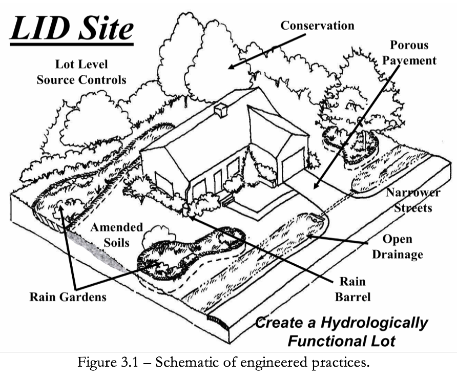 can be provided using the following engineered practices listed below. Figure 3.1 provides a schematic example of a combination of practices. Some potential applications of IMPs are discussed below.
- Bioretention or Rain Gardens – Vegetated depressions that collect runoff and either filter before discharge or infiltrate it into the ground.
- Dry Wells – Gravel- or stone-filled pits that are located to catch water from roof downspouts or paved areas.
- Filter Strips – Bands of dense vegetation planted immediately downstream of a runoff source designed to filter runoff before entering a receiving structure or water body.
- Grass Swales – Shallow channels lined with grass and used to convey and store runoff.
- Infiltration Trenches – Trenches filled with porous media such as bioretention material, sand, or aggregate that collect runoff and exfiltrate it into the ground.
- Permeable Pavement – Asphalt or concrete rendered porous by the aggregate structure.
- Permeable Pavers – Manufactured paving stones containing spaces where water can penetrate into the porous media placed underneath.
- Rain Barrels and Cisterns – Containers of various sizes that store the runoff delivered through building downspouts. Rain barrels are generally smaller structures, located above ground. Cisterns are larger, are often buried underground, and may be connected to the building’s plumbing or irrigation system.
- Soil amendments – Minerals and organic material added to soil to increase its capacity for infiltration, absorbing moisture and sustaining vegetation.
- Planter box filters – Curbside containers placed below grade, covered with a grate, filled with filter media and planted with a tree in the center.
- Vegetated Buffers – Natural or man-made vegetated areas adjacent to a waterbody, providing erosion control, filtering capability, and habitat.
- On-lot tree-save areas – Runoff can be directed to existing on-lot tree conservation areas to encourage stormwater retention.
- Small detention features – For example driveway culverts can be undersized to detain flow and encourage stormwater retention.
- Infiltration Swales – Swales designed with infiltration trenches.
3.2 Integrated Management Practices for High Density Industrial, Commercial and Residential Development
It is relatively easy to understand how LID principals and practices can be applied to single family residential development where there is ample space. High density development seems much more challenging with little green space available for LID practices. However, there is little difference in the application of LID site design principles nor the use of small scale engineered practices for volume and water quality control. The only difference is LID practices must be designed to accommodate building architecture, sidewalks, parking lots, streets and landscaping.
It is still important to optimize the conservation and use of natural resources and soils on the larger project level and where feasible minimize impacts internal to the site.
The examples shown in Figure 3.2 provide general LID design strategies for office buildings, small commercial buildings and big box sites. These site designs include a variety of techniques.
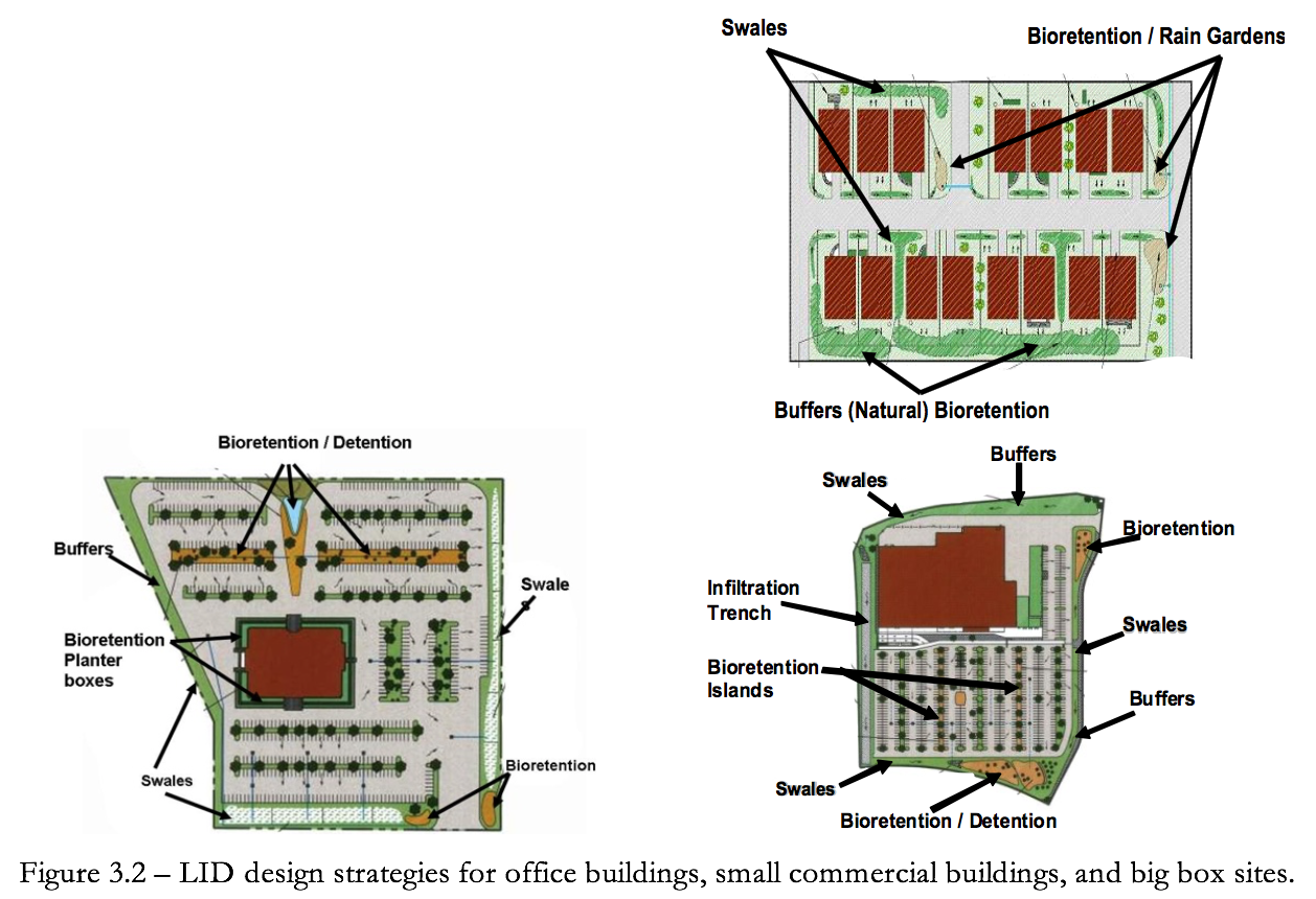
Typical LID techniques used for high-density developments include: perimeter buffers, swales and bioretention systems; parking lot bioretention/detention islands, planter boxes, green roofs, porous pavers/pavement and infiltration devices and underground storage. Runoff can be stored for use or controlled under buildings, parking lots and sidewalks using porous pavers and volume storage devices.
LID techniques can be integrated throughout the available green space using a range of bioretention techniques such as planter boxes, swales and street trees. In addition to the LID techniques previously listed, other engineered practices for high density development are included below. Figure 3.3 provides a schematic example.
- Planter Boxes – Bioretention systems within containers designed for filtration and or infiltration.
- Green Roofs – Vegetated roofs designed for retention / detention storage and, filtration.
- Underground Storage – Use of cisterns, pipes, vaults or other storage devices for retention or detention storage.
- Porous Pavers and Surfaces – Porous surfaces design in combination gravel storage or other.
- Manufactured Devices – Numerous commercial devices are available for filtration, screening, storage and treatment that can be integrated in the high density development.
- Building Architecture – Buildings can be designed to capture hold and use more runoff with, cisterns, planter boxes and wall planting systems.
3.3.1 Open Section Roadways
Open section roadways consist of a variable-width gravel or grass shoulder, usually wide enough to accommodate a parked car, and an adjoining grassed swale that conveys and treats runoff. When feasible, reducing road width provides greater opportunities to increase the width of grass shoulders and swales for treatment.
Street pavements width should be adjusted accordingly depending on off-street parking availability and shoulder requirements. Where feasible preserve existing vegetation and drainage features adjacent to the shoulder or swale. Also consider placing utilities under street pavements to eliminate conflicts with tree roots, grassed swales, and bioretention areas.
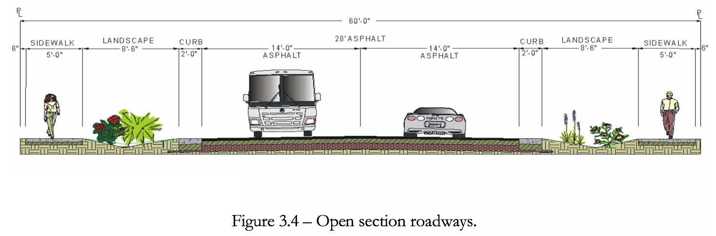
A primary goal of LID is to work with landscape hydrology and make it more functional (i.e., to use the surrounding landscape to absorb and filter water). Figure 3.4 shows a 60-foot roadway design with sidewalks on both sides. The important LID feature is the use of wider more functional swales for treatment and control. Notice that the swales are located between the road surface and sidewalks providing greater protection to pedestrians.
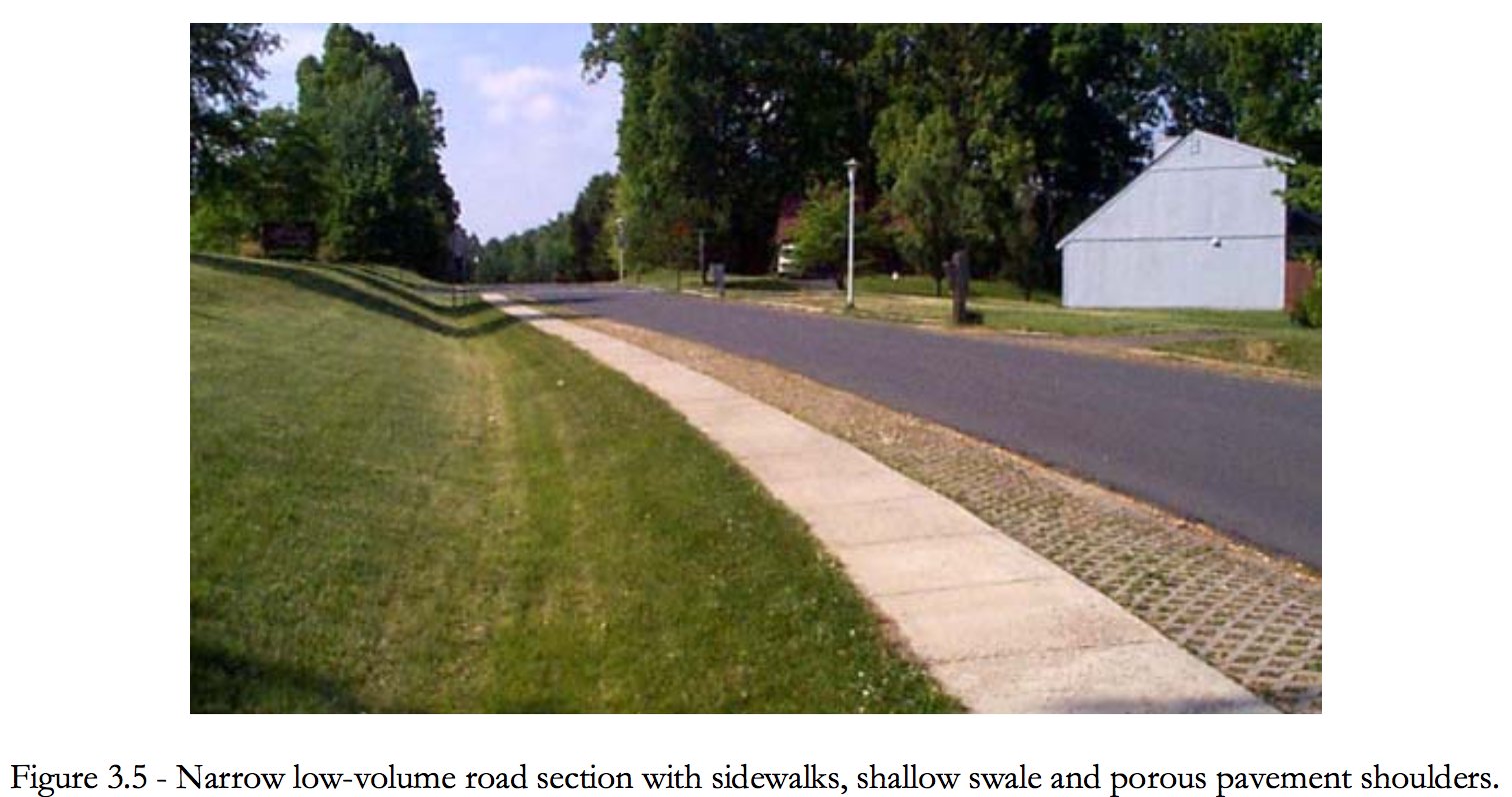
The figure below (Figure 3.5) shows a narrow road section with sidewalks, shallow swale and porous pavement shoulders. The paver blocks provide a rough surface to alert drives if their tires leave the road surface. The pavers also protect the edge of the asphalt surface from breaking off. Generally, very shallow and broad swales are preferred as they provide more surface area to treat and absorb runoff. Swale performance can be greatly enhanced when you can take advantage of infiltration.
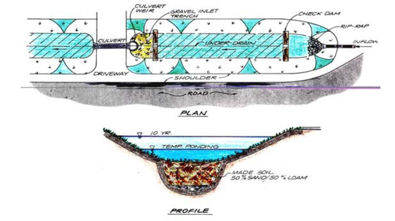
The figure below (Figure 3.6) shows an example of how to design a swale to enhance its ability to filter and infiltrate runoff. In this case several features have been incorporated into the design including using the culvert as a weir for detention control; check dams to increase ponding time and decrease velocities; trench drain along the bottom of the swale to encourage infiltration and increase runoff storage in the engineered soil. Road water quality treatment swales should be designed to be shallow with under drains if possible to encourage good drainage and discourage standing water and associated nuisance problems.
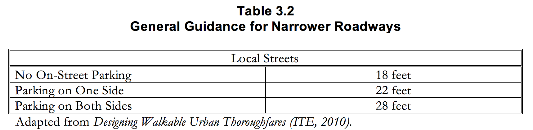
When it is possible to use narrower roadways the table below (Table 3.2) provides suggested general guidance. Even a narrow street width of 22 feet can still accommodate parking on one side of the roadway and leave ample room for a safe travel lane that is generous enough to accommodate most fire trucks, school buses, and garbage trucks.
Local Streets are intended to provide access to individual lots. They should provide low-speed bicycle and vehicle routes and while accommodating pedestrians. In comparison to other types of streets, local streets should generally be short in total distance.
In residential areas, “yield” local streets provide the preferred cross-section to encourage equal priority among all users. These streets are characterized by a relatively narrow unstriped travelway shared by all vehicles, and also have comfortable pedestrian facilities. “Narrow” local streets may be used where most parking is handled off-street. This is typical in a traditional neighborhood design (TND) context. Where on-street parking is expected to be more heavily used, yield streets may not be appropriate.
Each local street type should feature a 14-foot minimum clear travel path so as to appropriately accommodate emergency vehicles.
3.2.2 CUL-DE-SAC Designs
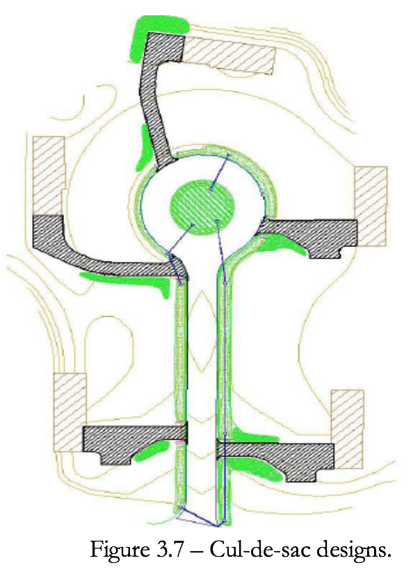
Homebuyers often prefer cul-de-sac properties for many reasons, and thus cul-de-sacs have become quite common. Depending on a subdivision’s lot size and street frontage requirements, five to ten houses can usually be located around a standard cul-de-sac perimeter. The bulb shape allows vehicles up to a certain turning radius to navigate the circle. To allow emergency vehicles to turn around, cul-de-sac radii can vary from as narrow as 30 feet to upwards of 60 feet, with right-of-way widths usually extending ten feet beyond these lengths. Figure 3.7 shows an open section roadway with on lot bioretention and a cul-de-sac with a bioretention area in the center for roadway runoff.
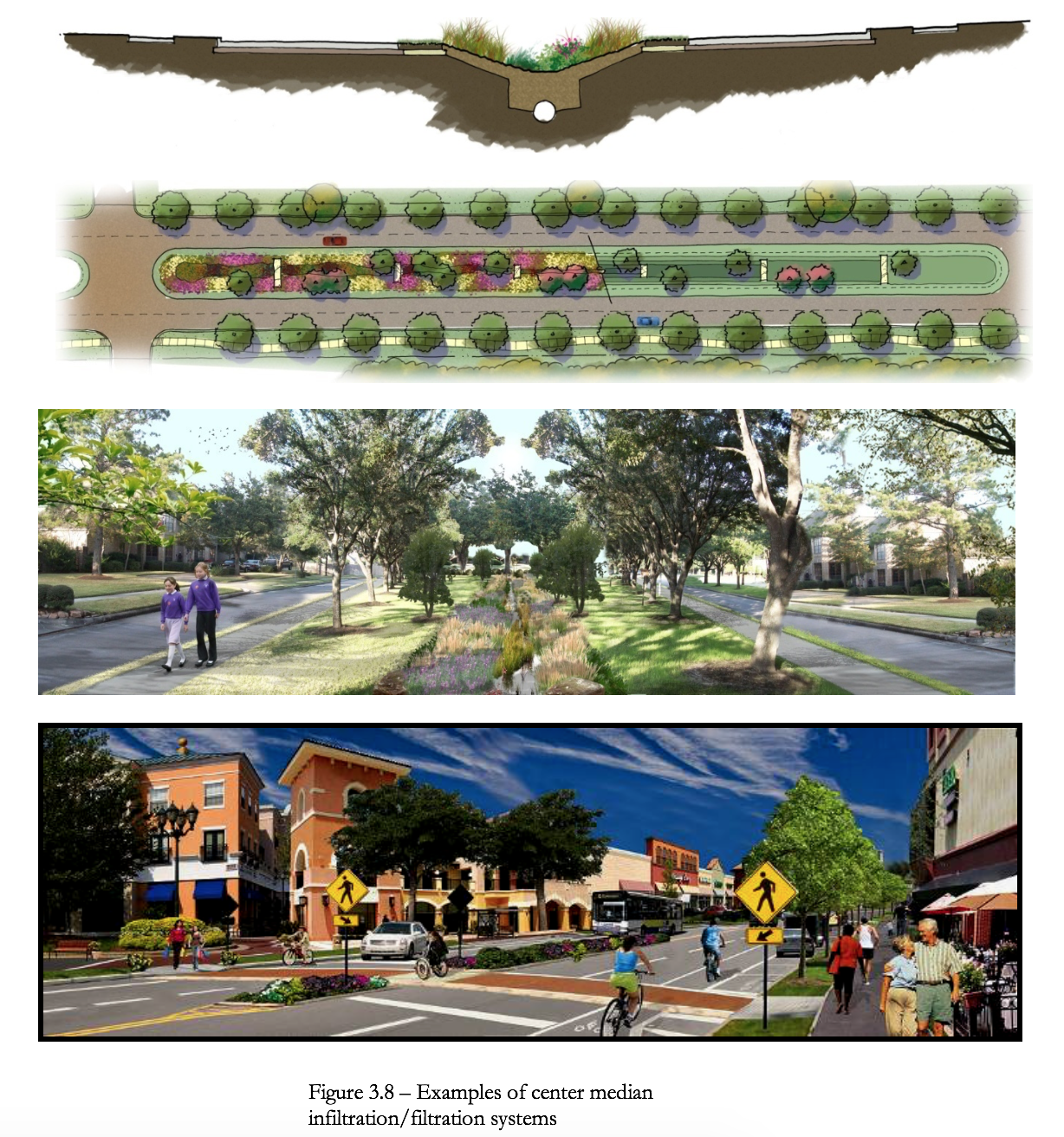
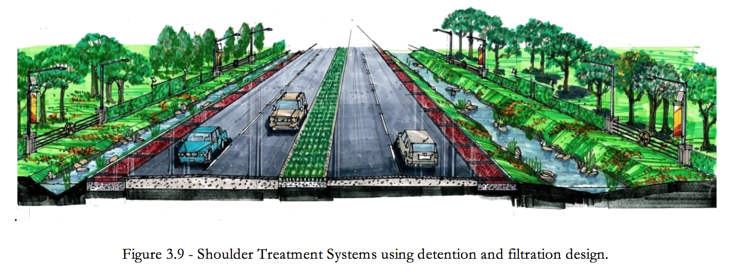
3.3.3 Divided Highways
The wider right-of-ways of divided highways provide many opportunities for LID practices on the shoulders and in the median. Figure 3.8 and Figure 3.9 provides examples of these options.
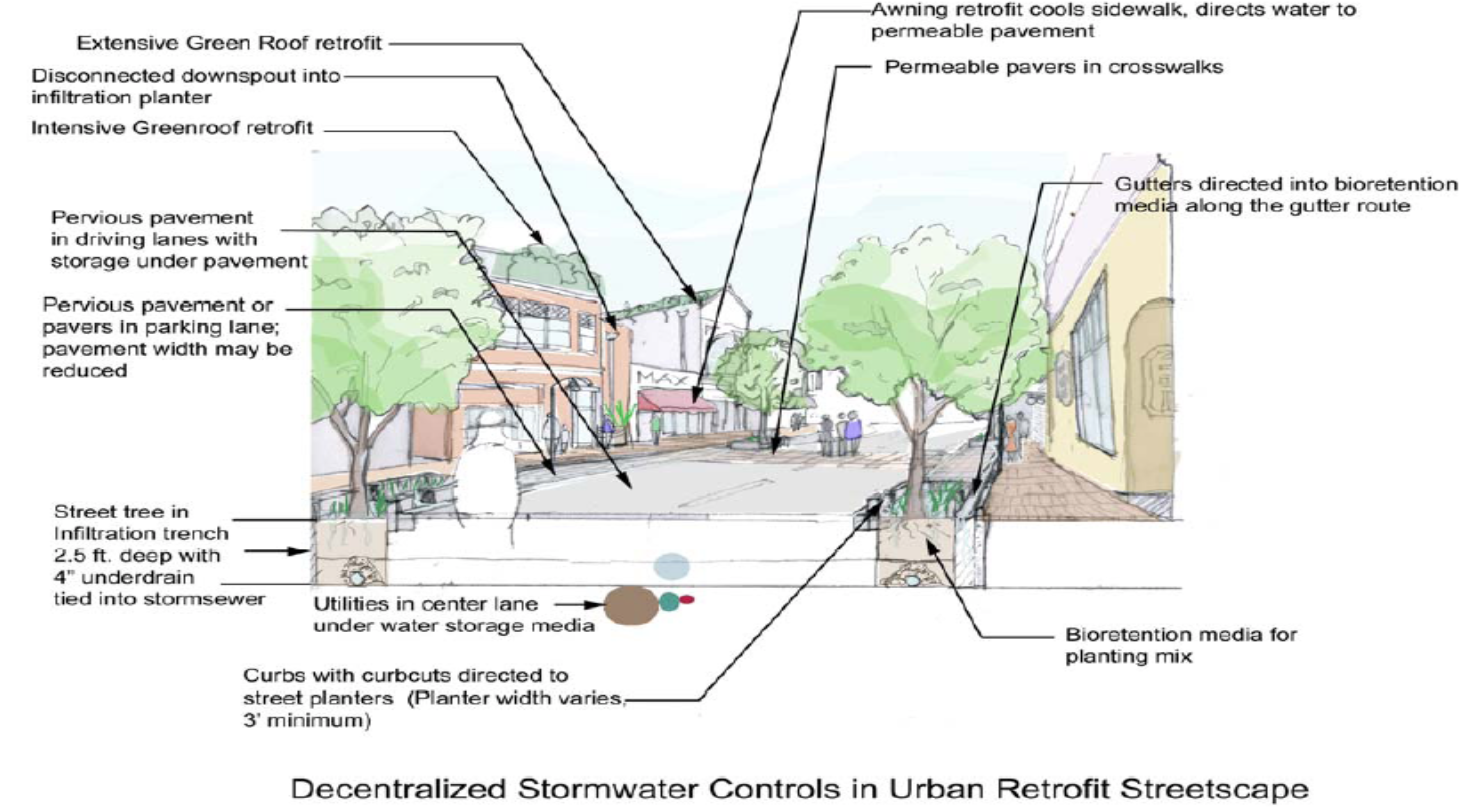
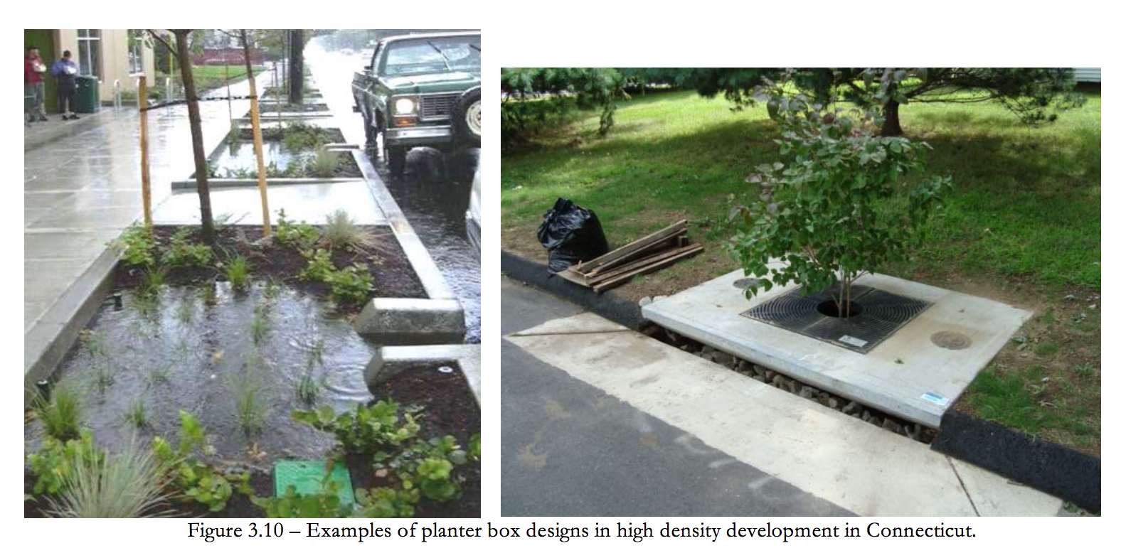
3.3.4 Highly Urbanized LID Street Design
Below are two examples of planter box designs in high density development (Figure 3.10). The image on the left is a slow flow system that requires very large surface areas to treat the water quality volume. The image on the right is a very high flow media system that has an extremely small foot print saving space reducing overall construction and maintenance costs. However, both provide the same water quality treatment benefits. Both systems can be designed with underground storage for detention infiltration or retention to be used for irrigation. There are many devices that can be used for underground storage ranging from metal, plastic or concrete pipes to a variety of plastic prefabricated storage devices.
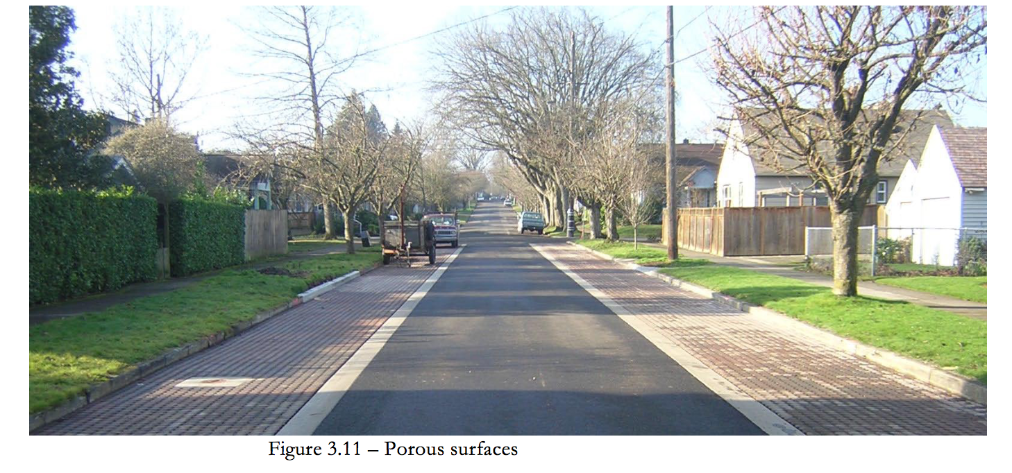
3.3.5 Porous Surfaces
Porous pavers, asphalt and concrete are all other design options to provide a hard surface suitable for roadways that allow runoff to percolate into underground gravel beds or other storage devices for detention or infiltration. An example is provided below as Figure 3.11. To reduce the cost these surfaces they should not be placed over the entire roadway but rather strategically placed and sized to allow sufficient runoff volume to enter the underlying storage device.
3.4.1 Retrofit Case Studies
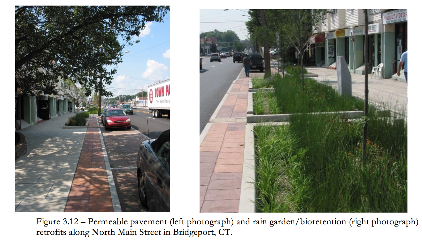
Retrofit and redevelopment projects utilizing LID techniques have been implemented throughout the country in recent years. Multiple projects have occurred in Connecticut. For example, a traffic control project calling for access management adjacent to North Main Street in the City of Bridgeport, CT, incorporated rain gardens/bioretention and permeable pavement into project design. Specifically, North Main Street was narrowed and permeable pavement was installed alongside portions of the roadway to accommodate vehicular parking and treat storm water runoff. Additionally, series of rain gardens were installed along the sidewalk to receive and treat storm water runoff. Photographs of the LID techniques implemented along Main Street are provided as Figure 3.12.
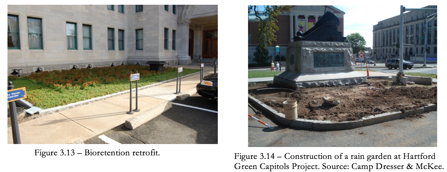
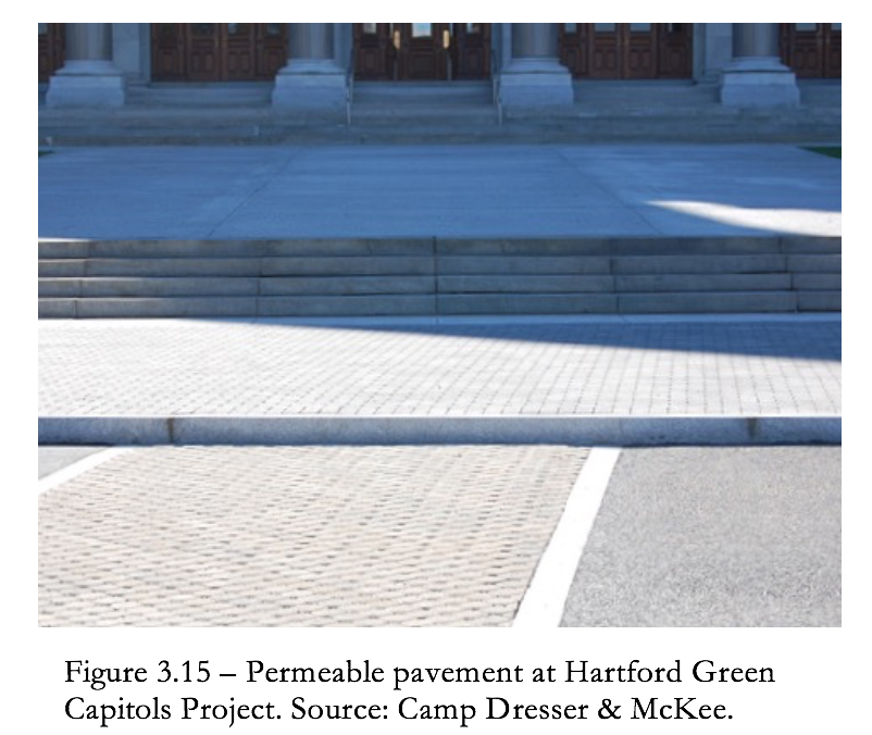
Another example of green infrastructure retrofit project is the Hartford Green Capitols project. This project focused on Connecticut’s capitol building in Harford, CT and included installation of porous pavement, green roofs, and rain gardens, as well as rain harvesting techniques. Such techniques served to improve water quality and educate state residents about green infrastructure. Photographs of the LID techniques implemented as part of the Hartford Green Capitols Project are provided as Figures 3.13-3.15.
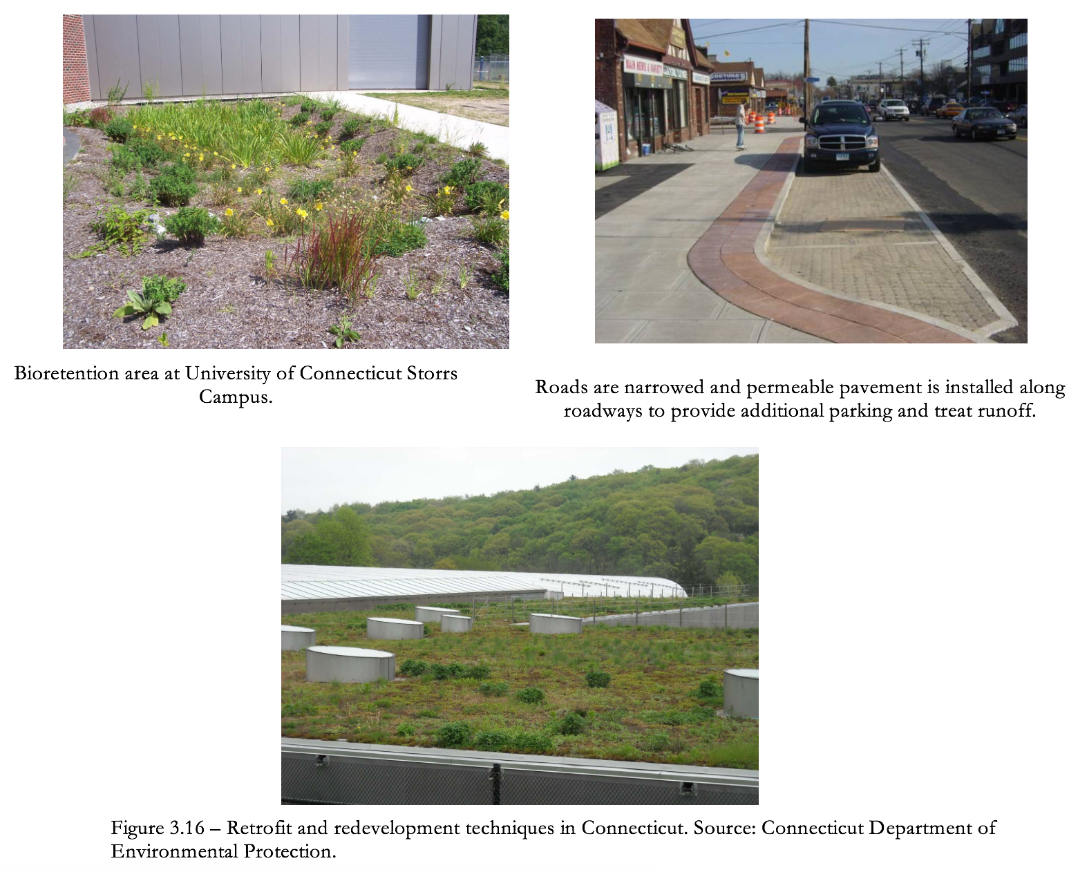
Additional examples of techniques used in Connecticut for both retrofit and redevelopment projects are provided as Figure 3.16.