Description
 Stormwater wetlands are constructed wetlands that incorporate marsh areas and permanent pools to provide enhanced treatment and attenuation of stormwater flows. Stormwater wetlands differ from stormwater ponds in that wetland vegetation is a major element of the overall treatment mechanism as opposed to a supplementary component. This section includes three types of stormwater wetlands:
- Shallow Wetland
- Extended Detention Shallow Wetland
- Pond/Wetland System.
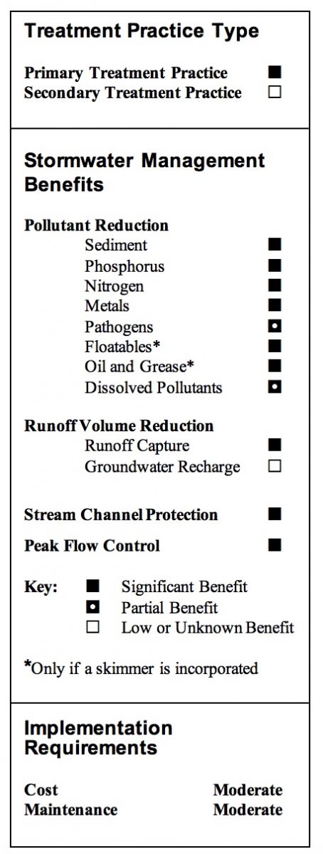
While stormwater wetlands can provide some of the ecological benefits associated with natural wetlands, these benefits are secondary to the function of the system to treat stormwater. Stormwater wetlands can be very effective at removing pollutants and reducing peak flows of runoff from developed areas. Removal of particulate pollutants in stormwater wetlands can occur through a number of mechanisms similar to stormwater ponds including sedimentation and filtration by wetland vegetation. Soluble pollutants can also be removed by adsorption to sediments and vegetation, absorption, precipitation, microbial decomposition, and biological processes of aquatic and fringe wetland vegetation. Stormwater wetlands are particularly advantageous when nitrogen and/or dissolved pollutants are a concern.
The key to maximizing pollutant removal effectiveness in stormwater wetlands is maintaining wet conditions adequate to support wetland vegetation. To achieve this, the constructed wetlands must either intercept the groundwater table or must be lined with an impermeable liner and have a watershed large enough to supply storm flows that will maintain wetness even during dry periods.
Stormwater wetland systems should be designed to operate on the plug flow principle where incoming water displaces the water retained in the system from the previous storm event. This is accomplished by maximizing length versus width ratios and/or by creating distinct cells along the treatment path. Ideally, the wetland system would be designed to retain the water quality volume (WQV) between storm events. As a result, storms that generate runoff less than the WQV would be entirely retained while only a percentage of the runoff from storms that generate more than the WQV would be retained. The value provided by this process is that a portion of the “new” polluted runoff is retained, and the “old” treated water is discharged from the wetland, thereby allowing extended treatment of the WQV.
Stormwater wetlands should be equipped with a sediment forebay or similar form of pretreatment to minimize the discharge of sediment to the primary treatment wetland. High solids loadings to the system will degrade system performance and result in more frequent cleaning, which could result in additional disturbance to the wetland vegetation. A micropool or permanent pool is also often included just prior to the discharge for additional solids removal.
Design Variations
There are several common stormwater wetland design variations. The various designs are characterized by the volume of the wetland in the deep pool, high marsh, and low marsh zones, and whether the design allows for detention of small storms above the permanent pool.
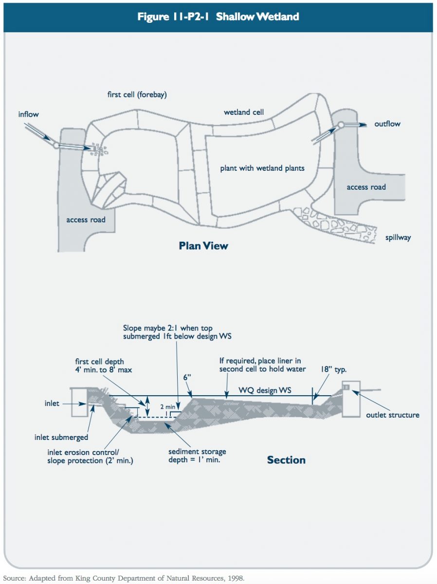
Shallow Wetland: Most shallow wetland systems, also referred to as shallow marsh wetlands, consist of aquatic vegetation with a permanent pool ranging from 6 to 18 inches during normal conditions. Shallow wetlands are designed such that flow through the wetlands is conveyed uniformly across the treatment area. While pathways, streams or other varied water depths could enhance the aesthetic or ecosystem value of the wetland, they could also allow cause short-circuiting through the wetland thereby reducing the overall treatment effectiveness. As a result, providing a uniformly sloped system is recommended to maximize treatment performance. In order to enhance plug flow conditions across the wetland, individual wetland cells can be constructed and separated by weirs. Figure 11-P2-1 depicts a typical schematic design of a shallow wetland.
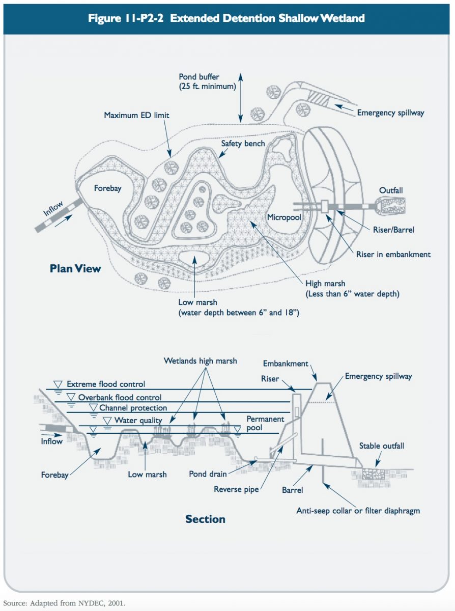
Extended Detention Shallow Wetland: Extended detention shallow wetlands provide a greater degree of downstream channel protection as they are designed with more vertical storage capacity. The additional vertical storage volume also provides extra runoff detention above the normal pool elevations. Water levels in the extended detention shallow wetland may increase by as much as three feet after a storm event and return gradually to pre-storm elevations within 24 hours of the storm event. The growing area in extended detention shallow wetlands extends from the normal pool elevation to the maximum water surface
elevation. Wetland plants that tolerate intermittent flooding and dry periods should be selected for the extended detention area above the shallow marsh elevations. Figure 11-P2-2 depicts a typical schematic design of an extended detention shallow wetland.
Pond/Wetland Systems: Multiple cell systems, such as pond/wetland systems, utilize at least one pond component in conjunction with a shallow marsh component. The first cell is typically a wet pond, which provides pretreatment of the runoff by removing particulate pollutants. The wet pond is also used to reduce the velocity of the runoff entering the system. The shallow marsh then polishes the runoff, particularly for soluble pollutants, prior to discharge. These systems require less space than the shallow marsh systems since more of the water volume is stored in the deep pool which can be designed to reduce peak flows. Because of this system’s ability to significantly reduce the velocity and volume of incoming peak flows (i.e., flow equalization or dampening), it can often achieve higher pollutant removal rates than other similarly sized stormwater wetland systems. Figure 11-P2-3 depicts a typical schematic design of a pond/wetland system.
![]()
Design Criteria
Wetland designs may vary considerably due to site constraints, local requirements, or the designer’s preferences. The five common design elements that should be considered for all stormwater wetlands are:
* Pretreatment
* Treatment
* Conveyance
* Maintenance reduction
* Landscaping.
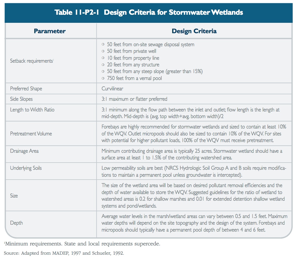
Design considerations for stormwater wetlands are presented below and summarized in Table 11-P2-1.
Forebay
A sediment forebay is recommended for all stormwater wetland systems. Sediment forebays provide pretreatment by settling out coarse solids, which enhances treatment performance, reduces maintenance, and increases the longevity of the system. This is especially critical in wetland systems where removal of solids would disturb existing wetland vegetation and temporarily affect treatment performance.
* The forebay should be sized to contain at least 10% of the WQV and have an adequate depth to prevent resuspension of collected sediments during the design storm, often being four to six feet deep. Maintaining water depths in excess of 4 feet precludes invasive emergent vegetation such as cattails. Emergent vegetation provides mosquito larvae with refuge from predators and increases nutrient availability.
* In larger open water areas of the wetland system (forebay and micropool), maintain water quality sufficient to support mosquito-feeding fish. Stormwater ponds and wetlands often develop mini-ecosystems where birds, frogs, and other insects feed, many of which are natural predators of mosquitoes and nuisance insects. Ponds can also be stocked with predatory fish native to Connecticut that feed on mosquito larvae such as banded sunfish, flathead minnows, Eastern mud minnows, and several species of killfish. The DEP Fisheries Division should be consulted regarding species selection. Other natural predators of mosquitoes such as dragonfly nymphs can also be used.
* The forebay must also include additional sediment storage volume that may not be used for WQV calculations.
* The outlet from the forebay should be designed in a manner to both evenly distribute flow across the wetland/marsh area as well as prevent erosion of the embankment. This outlet can be configured in a number of ways including a culvert with a distribution header or spillway channel. The outlet should be designed to safely convey the same design flow that is proposed to enter the basin. The outlet invert must be elevated in a manner such that 10% of the WQV can be stored below it in addition to the required sediment volume.
* The forebay should have a minimum length to width ratio of 2:1 and a preferred length to width ratio of 3:1.
* Direct access for appropriate maintenance equipment should be provided to the forebay and may include a ramp to the bottom if equipment cannot reach all points within the forebay from the top. The forebay can be lined with a concrete pad to allow easier removal of sediment and to minimize the possibility of excavating subsurface soils or undercutting embankments during routine maintenance.
* A fixed vertical sediment depth marker should be installed in the forebay to measure sediment deposition.
* A barrier, such as an earthen berm, gabions, or a concrete weir may be used to separate the forebay from the permanent pool. This barrier should be armored as necessary to prevent erosion of the embankment if it overtops. This armoring could consist of materials such as riprap, pavers, or geosynthetics designed to resist slope erosion.
* Additional pretreatment can be provided in the forebay by raising the embankment to provide some detention of incoming flows.
* Sediment storage capacity should be provided in the forebay as calculated by the Universal Soil Loss Equation in the Connecticut Guidelines for Soil Erosion and Sediment Control.
Wetland/Marsh Area
The size of the wetland/marsh area should be based on pollutant influent concentrations, base flow, peak design flow, and desired effluent concentrations. Kadlec and Knight (1996) have developed area-based, first-order wetland design models to predict treatment area requirements. The use of these models is recommended to size the wetland areas. This model is as follows:
General Model:
J = k (C – C*) ; where
k = k20 Θk(T-20)
C* = C*20 Θc(T-20)
| Where: | J | = | Removal rate (g/m2/yr) |
| k | = | First-order, area-based rate constant (m/yr) | |
| k20 | = | Rate constant at 20°C (m/yr) | |
| C | = | Pollutant concentration (mg/L) | |
| C* | = | Irreducible background concentration (mg/L) | |
| C*20 | = | Irreducible background concentration at 20°C (mg/L) | |
| T | = | Temperature, °C | |
| Θc | = | Temperature coefficient for background concentration | |
| Θk | = | Temperature coefficient for rate constant |
Wetland Area (based on modified plug-flow hydraulics):
A = Q / HLR = - Q/k (ln ((C2 - C*)/(C1 - C*))
| Where: | HLR | = | Hydraulic loading rate (m/yr) |
| A | = | Wetland area at normal pool elevation (m2), excluding habitat islands | |
| Q | = | Design inflow rate (m3/yr) | |
| C1 | = | Inflow concentration (mg/L) | |
| C2 | = | Outflow concentration (mg/L) |
Model Parameter Values (at 20°C):
| BOD | TSS | NH3-N | NO3+NO2-N | TN | TP | |
| K20, m/yr | 35 | 1,000 | 18 | 35 | 22 | 12 |
| Θk | 1.00 | 1.00 | 1.04 | 1.09 | 1.05 | 1.00 |
| C20, mg/L | 6 | 5.1+0.16C1 | 0.0 | 0.0 | 1.5 | 0.02 |
| Θc | - | 1.065 | - | - | - | 1.00 |
BOD = biochemical oxygen demand
TSS = total suspended solids
NH3-N = ammonia nitrogen
NO3+NO2-N = nitrate and nitrite nitrogen
TN = total nitrogen
TP = total phosphorus
In order to better simulate plug flow conditions and minimize short-circuiting, individual wetland cells can be constructed along the flow path. Weirs, berms, or shallow marsh areas can be used to form these cells. However, the cells should be designed such that flow is redistributed along the edge of each cell. To reduce the potential for mosquito breeding, incorporate contiguous marsh areas rather than isolated pockets and slope the marsh areas to the deepest pool.
Infiltration Design and Water Balance
The rate of infiltration through the bottom of the wetland can be estimated by using Darcy’s law. For most wetlands, the rate of infiltration is relatively constant. Wetlands act as storage reservoirs, retaining water during precipitation events and releasing it slowly as outlet flow and infiltration. During summer months when evapotranspiration losses are large, pool levels commonly drop episodically below the design operating level and outflow ceases.
Ideally, wetlands should not completely dewater under conditions of normal precipitation. To identify potential problems, a monthly water balance should be analyzed for the proposed wetland. The pool level at the end of each month can be estimated as follows:
PL = PL0 + [BF + (PR x AW) + (PR x AD x RO) – (ET x AW) – (I x A)] / A
| Where: | PL | = | Pool depth at the end of month (feet) |
| PL0 | = | Pool depth from the previous month (feet) | |
| BF | = | Total monthly flow into the wetland (acre-feet) | |
| PR | = | Total monthly precipitation (feet) | |
| AW | = | Area of wetland (acres) | |
| AD | = | Area of tributary drainage (acres) | |
| RO | = | Weighted Volumetric Runoff Coefficient | |
| ET | = | Monthly potential evapotranspiration (feet) | |
| A | = | Area inundated at depth PL0 (acres) | |
| I | = | Monthly infiltration (feet) |
If the calculated pool depth at the end of the month is greater than the normal pool depth established at the outlet, then outflow will occur during that month. The quantity is not important. In months with a net outflow, the beginning pool depth for the next month will equal the normal pool depth.
Tables or equations for estimating potential evapotranspiration are available from many sources, including Kadlec and Knight (1996). However, for conceptual design purposes, wetland evapotranspiration can be estimated as 80 percent of the pan evaporation rate.
In most wetlands, the area that is inundated varies with depth. The normal operating pool depth also may be adjusted seasonally to accommodate changes in the water budget. These factors should be accounted for in the calculation. If the water balance predicts that the wetland will dewater, design modifications can be considered, including:
* Reducing the infiltration rate by adding a clay layer or synthetic liner
* Relocating the proposed wetland to increase the contributing drainage area
* Increasing the normal operating pool level.
Limitations on increasing the normal pool level will be imposed by the need for shallow water habitat to support emergent plant vegetation. Short periods during which the wetland becomes dry may be tolerated in some instances. However, the selection of plants must be tailored to accommodate these adverse conditions and special considerations will be required for the maintenance of the wetland during dry periods.
Conveyance
Stormwater should be conveyed to and from all stormwater management practices safely and to minimize erosion potential.
Inlet Protection
* The number of inlets should be minimized, and one inlet is preferable. The inlet should be located at the most hydraulically remote point from the outlet, but in any case should be located in a manner that meets or exceeds desired length to width ratios.
* Inlet areas should be stabilized to ensure that non-erosive conditions exist for the design storm event.
* The ideal inlet discharge configuration is above the permanent pool to prevent potential hydraulic impacts from freezing.
Outlet Protection
* The channel immediately below an outfall should be modified to prevent erosion and conform to natural topography by use of a plunge pool or a riprap pad and sized for peak discharge velocities.
* Outlet protection should be used to reduce flow to non-erosive velocities from the principal spillway based on actual cover and soil conditions (3.5 to 5.0 ft/s).
* If a pond outlet discharges to a perennial stream or channel with dry weather base flow, tree clearing should be minimized and a forested riparian zone re-established.
* To convey potential flood flows from the basin, an armored emergency spillway should be provided
Wetland Liners
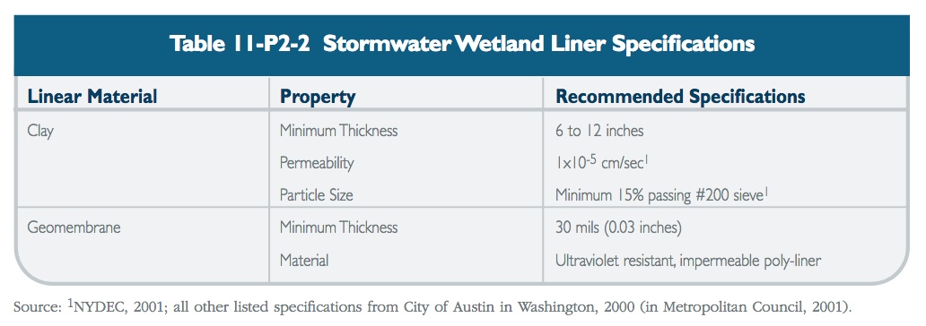
* When the permanent pool does not intercept groundwater, a liner may be needed to maintain minimum water levels. Liners are also necessary for wetland systems that may present a risk to groundwater quality. Table 11-P2-2 lists recommended specifications for clay and geomembrane liners.
Pool Benches
These specifications apply to permanent pools at the sediment forebay and micropool.
* For side slopes steeper than 4:1, provide a 10-foot wide flat safety bench above the permanent pool level.
Vegetation
High pollutant removal efficiencies are dependent on a dense cover of emergent plant vegetation. Actual plant species do not appear to be as important as plant growth habitat. In particular, plants should be used that have high colonization and growth rates, can establish large surface areas that continue through the winter dormant season, have high potential for treating pollutants, and are very robust in flooded environments. Appendix A contains planting guidance for stormwater wetlands. Other landscaping criteria include the following:
* Soils should be modified to mitigate compaction that occurs during construction around the proposed planting sites.
* Woody vegetation may not be planted or allowed to grow within 25 feet of the toe of the embankment and 25 feet from the principal spillway structure.
* Existing trees should be preserved in the buffer area during construction. It is desirable to locate forest conservation areas adjacent to ponds and wetlands. To help discourage resident geese populations, the buffer can be planted with trees, shrubs, and native ground covers.
* Annual mowing of the pond/wetland buffer is only required along maintenance rights-of-way and the embankment. The remaining buffer can be managed as a meadow (mowing every other year) or forest.
Maintenance Reduction Features
In addition to regular maintenance activities needed to maintain the function of stormwater practices, some design features can be incorporated to ease the maintenance burden of each practice. In constructed wetlands, maintenance reduction features include techniques to reduce the amount of required maintenance, as well as techniques to make regular maintenance activities easier.
* Outlets should be designed with non-clogging features, such as a weir, or by incorporating trash racks for culverts and orifice openings.
* To prevent clogging from ice or floatables, a reverse slope outlet pipe can be used to draw water from below the permanent pool up to the outlet structure. The invert of the pipe drawing from the pool should be at least 18 inches from the bottom to prevent sediment discharge.
* Orifices should be no smaller than 6 inches in diameter, and have a trash rack to prevent clogging.
* Pools should have a manually operated drain to draw down the pond for infrequent maintenance or dredging of the main cell of the pond.
* Metal components of outlet structures should be corrosion resistant, but not galvanized due to the contribution of zinc to water (Washington, 2000).
* Outlet structures should be resistant to frost heave and ice action in the pond.
Cold Climate Design Considerations
The following design elements should be considered to minimize potential performance impacts caused by cold weather:
* Inlet pipes should not be submerged, since this can result in freezing and upstream damage or flooding.
* Bury pipes below the frost line to prevent frost heave and pipe freezing.
* Increase the slope of inlet pipes to a minimum of 1%, if site conditions allow, to prevent standing water in the pipe and reduce the potential for ice formation.
* If perforated riser pipes are used, the minimum orifice diameter should be 0.5 inches. In addition, the pipe should have a diameter of at least 6 inches.
* When a standard weir is used, the minimum slot width should be 3 inches, especially when the slot is tall.
* Baffle weirs can prevent ice formation near the outlet by preventing surface ice from blocking the inlet, encouraging the movement of base flow through the system.
* Riser hoods and reverse slope pipes should draw from at least 6 inches below the typical ice layer. This design encourages circulation in the pond, preventing stratification and formation of ice at the outlet. Reverse slope pipes should not be used for off-line ponds.
* Trash racks should be installed at a shallow angle to prevent ice formation.
* Additional storage should be provided to account for storage lost to ice buildup, especially in shallow wetlands where much of the pool becomes frozen. Ice thickness may be estimated by consulting with local authorities (the fire department, for example) with knowledge of the typical ice thickness in the area.