Oil/Particle Separators (2004)

Description

Oil/particle separators, also called oil/grit separators, water quality inlets, and oil/water separators, consist of one or more chambers designed to remove trash and debris and to promote sedimentation of coarse materials and separation of free oil (as opposed to emulsified or dissolved oil) from stormwater runoff. Oil/particle separators are typically designed as off-line systems for pretreatment of runoff from small impervious areas, and therefore provide minimal attenuation of flow. Due to their limited storage capacity and volume, these systems have only limited water quality treatment capabilities. While oil/particle separators can effectively trap floatables and oil and grease, they are ineffective at removing nutrients and metals and only capture coarse sediment.

Several conventional oil/particle separator design variations exist, including:

* Conventional gravity separators (water quality inlets)

* Coalescing plate (oil/water) separators

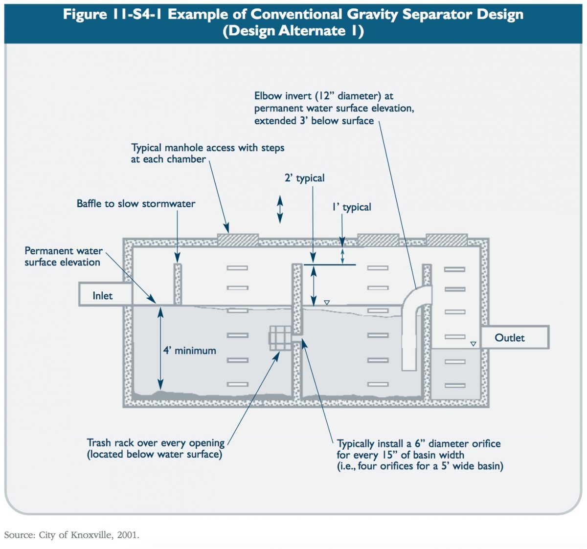
Conventional gravity separators (also called American Petroleum Institute or API separators) typically consist of three baffled chambers and rely on gravity and the physical characteristics of oil and sediments to achieve pollutant removal. The first chamber is a sedimentation chamber where floatable debris is trapped and gravity settling of sediments occurs. The second chamber is designed primarily for oil separation, and the third chamber

provides additional settling prior to discharging to the storm drain system or downstream treatment practice. Many design modifications exist to enhance system performance including the addition of orifices, inverted elbow pipes and diffusion structures. Figures 11-S4-1 and 11-S4-2 illustrate several examples of conventional gravity separator designs.

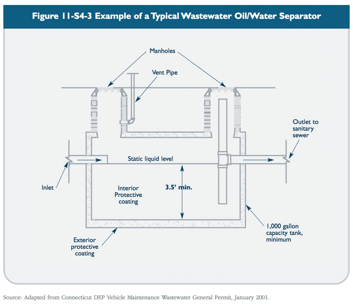
Conventional gravity separators used for stormwater treatment are similar to wastewater oil/water separators, but have several important differences. Figure 11-S4-3 shows a typical oil/water separator designed to treat wastewater discharges from vehicle washing and floor drains. As shown in the figure, wastewater separators commonly employ a single chamber with tee or elbow inlet and outlet pipes. The magnitude and duration of stormwater flows are typically much more variable than wastewater flows and, therefore, the single-chamber design does not provide sufficient protection against re-suspension of sediment during runoff events. Single-chamber wastewater oil/water separators should not be used for stormwater applications.

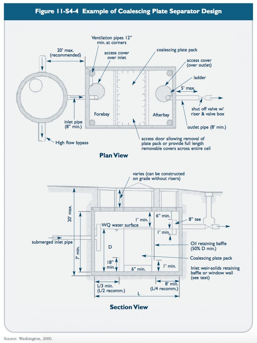
The basic gravity separator design can be modified by adding coalescing plates to increase the effectiveness of oil/water separation and reduce the size of the required unit. A series of coalescing plates, constructed of oil-attracting materials such as polypropylene and typically spaced an inch apart, attract small oil droplets which begin to concentrate until they are large enough to float to the water surface and separate from the stormwater (EPA, 1999). Figure 11-S4-4 shows a typical coalescing plate separator design.

A number of recently developed proprietary separator designs also exist. These are addressed in the Hydrodynamic Separators section of this chapter.

Reasons for Limited Use

* Limited pollutant removal. Cannot effectively remove soluble pollutants or fine particles.

* Can become a source of pollutants due to re-suspension of sediment unless maintained frequently. Maintenance often neglected (“out of sight and out of mind”).

* Limited to relatively small contributing drainage areas.

Suitable Applications

* For limited removal of trash, debris, oil and grease, and sediment from stormwater runoff from relatively small impervious areas with high traffic volumes or high potential for spills such as:

  • Parking lots
  • Streets
  • Truck loading areas
  • Gas stations
  • Refueling areas
  • Automotive repair facilities
  • Fleet maintenance yards
  • Commercial vehicle washing facilities
  • Industrial facilities.

* To provide pretreatment for other stormwater treatment practices.

* For retrofit of existing stormwater drainage systems, particularly in highly developed (ultra-urban) areas.

Design Considerations

* Drainage Area: The contributing drainage area to conventional oil/particle separators generally should be limited to one acre or less of impervious cover. Separators should only be used in an off-line configuration to treat the design water quality flow (peak flow associated with the design water quality volume). Upstream diversion structures can be used to divert higher flows around the separator. On-line units receive higher flows that cause increased turbulence and re-suspension of settled material (EPA, 1999).

* Sizing/Design: The combined volume of the permanent pools in the chambers should be 400 cubic feet per acre of contributing impervious area. The pools should be at least 4 feet deep, and the third chamber should also be used as a permanent pool.

* A trash rack or screen should be used to cover the discharge outlet and orifices between chambers. An inverted elbow pipe should be located between the second and third chambers, and the bottom of the elbow pipe should be at least 3 feet below the second chamber permanent pool. Each chamber should be equipped with manholes and access steps/ladders for maintenance and cleaning. Potential mosquito entry points should be sealed (adult female mosquitoes can use openings as small as 1/16 inch to access water for egg laying).

* Maintenance: Maintenance is critical for proper operation of oil/particle separators. Separators that are not maintained can be significant sources of pollution. Separators should be inspected at least monthly and typically need to be cleaned every one to six months. Typical maintenance includes removal of accumulated oil and grease, floatables, and sediment using a vacuum truck or other ordinary catch basin cleaning equipment.

Plans for oil/particle separators should identify detailed inspection and maintenance requirements, inspection and maintenance schedules, and those parties responsible for maintenance.

* Sediment Disposal: Polluted water or sediment removed from separators should be properly handled and disposed in accordance with local, state, and federal regulations. Before disposal, appropriate chemical analysis of the material should be performed to determine proper methods for storage and disposal.

References

Connecticut Department of Environmental Protection (DEP). 2001. General Permit for the Discharge of Vehicle Maintenance Wastewater. Issuance Date January 23, 2001.

City of Knoxville. 2001. Knoxville BMP Manual. City of Knoxville Engineering Department. Knoxville, Tennessee.

United States Environmental Protection Agency (EPA). 2002. National Menu of Best Management Practices for Stormwater Phase II.

URL: http://www.epa.gov/npdes/menuofbmps/menu.htm, Last Modified January 24, 2002.

United States Environmental Protection Agency (EPA). 1999. Storm Water Technology Fact Sheet: Water Quality Inlets. EPA 832-F-99-029. Office of Water. Washington, D.C.

Washington State Department of Ecology (Washington). 2000. Stormwater Management Manual for Western Washington, Final Draft. Olympia, Washington.